12.7 H: TERMINALS
618 SIEPCYEUOQ2V01A Q2V Technical Manual
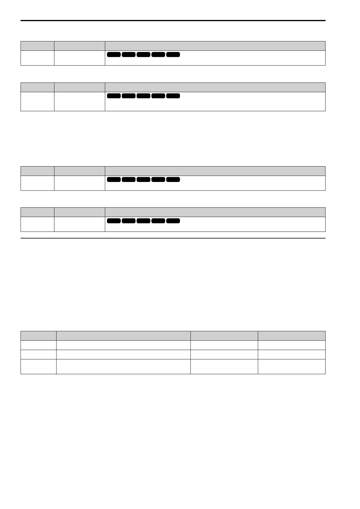
■ 15: OutFLowLimSel
Setting Value Function Description
15 OutFLowLimSel
Enters a signal to adjust the output frequency lower limit level as a percentage of the maximum output frequency.
■ 16: Mot PTC Input
Setting Value Function Description
16 Mot PTC Input
Uses the motor Positive Temperature Coefficient (PTC) thermistor to prevent heat damage to the motor as a percentage of the
current value when the 10 V analog signal is input.
• You can use the Positive Temperature Coefficient (PLC) thermistor as an auxiliary or alternative detection
function for oL1 [Motor Overload] problems to help prevent heat damage to motors. If the PTC input signal is
more than the overload alarm level, oH3 [Motor Overheat (PTC Input)] will flash on the keypad.
• If the drive detects oH3, the motor stops with the method set in L1-03. If the drive detects oH4, the motor stops
with the method set in L1-04. If the drive incorrectly detects motor overheating problems, set L1-05.
■ 30: Q2pack AI1
Setting Value Function Description
30 Q2pack AI1
Use with Q2pack. Refer to the Q2pack online manual for more information.
■ 31: Q2pack AI2
Setting Value Function Description
31 Q2pack AI2
Use with Q2pack. Refer to the Q2pack online manual for more information.
◆ H4: ANALOG OUTPUTS
H4 parameters set the drive analog monitors. These parameters select monitor parameters, adjust gain and bias,
and select output signal levels.
■ Calibrate Meters Connected to MFAO Terminal AO
Use these parameters to calibrate meters connected to terminal AO:
• H4-02 [AO An.Out Gain]
• H4-03 [AO An.Out Bias]
Set these parameters where the output voltage of 10 V and output current of 20 mA are 100% of the signal level.
Use jumper switch S5 and parameter H4-07 [AO Signal Level Select] to set the voltage output and current output.
No. Name Range Default
H4-02 AO An.Out Gain -999.9 - +999.9% 100.0%
H4-03 AO An.Out Bias -999.9 - +999.9% 0.0%
H4-07 AO Signal Level Select
1: 0 - 10 VDC
3: 4 - 20 mA
1
Figure 12.97 and Figure 12.98 show the gain and bias.

 Loading...


