Parameter Details
12
12.7 H: TERMINALS
SIEPCYEUOQ2V01A Q2V Technical Manual 617
■ 12: AcDcTimeGain
Setting Value Function Description
12 AcDcTimeGain
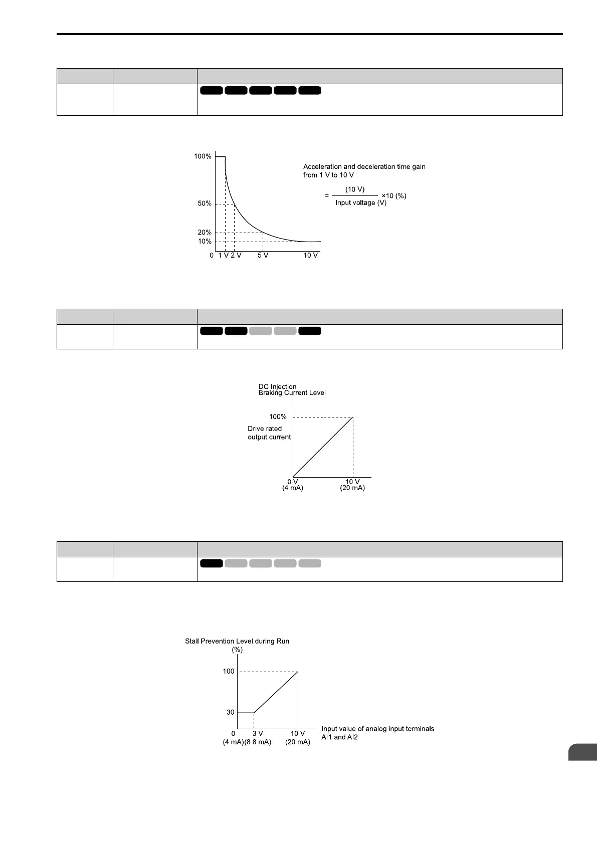
Enters a signal to adjust the gain used for C1-01 to C1-08 [Acceleration/Deceleration Times 1 to 4] and C1-09 [Fast Stop Time]
when the full scale analog signal (10 V or 20 mA) is 100%.
When you enable C1-01 [Accel Time 1], the acceleration time is:
Acceleration Time 1 = Setting value of C1-01 × acceleration and deceleration time gain / 100
Figure 12.94 Acceleration/Deceleration Time Gain through Analog Input
■ 13: DCInjBrakCurr
Setting Value Function Description
13 DCInjBrakCurr
Enters a signal to adjust the current level used for DC Injection Braking when the drive rated output current is 100%.
Note:
When you set this function, it will disable the setting value of b2-02 [DCI Braking Current].
Figure 12.95 DC Injection Braking Current through Analog Input
■ 14: StallPLev@Rn
Setting Value Function Description
14 StallPLev@Rn
Enters a signal to adjust the stall prevention level during run if the drive rated current is 100%.
Note:
The drive will use the smaller value of these values for Stall Prevent Level during Run:
• Multi-function analog input terminal analog input value
• L3-06 [StallP Level@Run]
Figure 12.96 Stall Prevention Level during Run with Analog Input

 Loading...


