12.6 F: OPTIONS
546 SIEPCYEUOQ2V01A Q2V Technical Manual
Note:
When A1-02 = 0 [Control Method = V/f Control], set H6-01 = 3 [PI Pulse Train Function = PG Feedback] to enable this parameter.
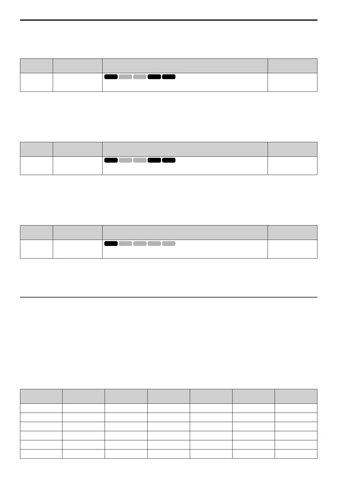
■ F1-10: Speed Dev Level
No.
(Hex.)
Name Description
Default
(Range)
F1-10
(0389)
Speed Dev Level
Sets the detection level of dEv [Speed Deviation] as a percentage when the maximum output
frequency is 100%.
10%
(0 - 50%)
When the speed deviation between the frequency reference and the actual motor speed is more than the value set
in F1-10 for longer than the time set in F1-11 [Speed Dev Delay Time], the drive will detect dEv.
Note:
When A1-02 = 0 [Control Method = V/f Control], set H6-01 = 3 [PI Pulse Train Function = PG Feedback] to enable this parameter.
■ F1-11: Speed Dev Delay Time
No.
(Hex.)
Name Description
Default
(Range)
F1-11
(038A)
Speed Dev Delay Time
Sets the length of time that the difference between the frequency reference and speed feedback
must be more than the level in F1-10 to cause dEv [Speed Deviation].
0.5 s
(0.0 - 10.0 s)
When the speed deviation between the frequency reference and the actual motor speed is more than the value set
in F1-10 [Speed Dev Level] for longer than the time set in F1-11, the drive will detect dEv.
Note:
When A1-02 = 0 [Control Method = V/f Control], set H6-01 = 3 [PI Pulse Train Function = PG Feedback] to enable this parameter.
■ F1-14: Enc PGOpen Time for Detection
No.
(Hex.)
Name Description
Default
(Range)
F1-14
(038D)
Enc PGOpen Time for
Detection
Sets the length of time that the drive must not receive a pulse signal to cause PGo [Encoder (PG)
Feedback Loss].
2.0 s
(0.0 - 10.0 s)
If the drive does not detect ouput pulses from the encoder for the time set in F1-14, it will trigger PGo.
Note:
• When A1-02 = 0 [Control Method = V/f Control], set H6-01 = 3 [PI Pulse Train Function = PG Feedback] to enable this parameter.
• Motor speed and load conditions can cause ov [Overvoltage] and oC [Overcurrent] faults.
◆ F6: COMMUNICATIONS, F7: ETHERNET
F6 and F7 parameters are used to set the basic communication settings and method of fault detection for the
communication option card. The communication option card parameters include common option card parameters
and communication protocol-specific parameters.
The following table lists the parameters that need to be set for each communication option card.
Refer to the technical manual for each communication option card for more information on installing, wiring, and
configuring the details needed before starting communication.
WARNING! Sudden Movement Hazard. Do test runs and examine the drive to make sure that the command references are
correct. If you set the command reference incorrectly, it can cause damage to the drive or serious injury or death.
Table 12.30 Correspondence Between Communication Protocols and Parameters (SI-C3, SI-T3, SI-ET3, SI-P3, SI-S3,
and SI-ES3)
Parameter
CC-Link
SI-C3
MECHATROLINK-II
SI-T3
MECHATROLINK-III
SI-ET3
PROFIBUS-DP
SI-P3
CANopen
SI-S3
EtherCAT
SI-ES3
F6-01 to F6-03 x x x x x x
F6-04 x - - - - -
F6-06 to F6-08 x x x x x x
F6-10, F6-11 x - - - - -
F6-14 x x x x x x
F6-16 x x x x x x

 Loading...


