Electrical Installation
3
3.5 Control Circuit Wiring
SIEPCYEUOQ2V01A Q2V Technical Manual 75
*2 Install the wire jumpers between terminals DIC-D24V and DIC-D0V to set the MFDI power supply (sinking/sourcing mode or
internal/external power supply).
NOTICE: Do not close the circuit between terminals D24V and D0V. A closed circuit between these terminals will cause
damage to the drive.
• Sinking Mode: Install a jumper between terminals DIC and D24V.
NOTICE: Do not close the circuit between terminals DIC and D0V. A closed circuit between these terminals will cause
damage to the drive.
• Sourcing Mode: Install a jumper between terminals DIC and D0V.
NOTICE: Do not close the circuit between terminals DIC and D24V. A closed circuit between these terminals will cause
damage to the drive.
• External Power Supply: No jumper is necessary between terminals DIC-D0Vand terminals DIC-D24V.
*3 The maximum output current capacity for terminal +10Von the control circuit is 20 mA.
NOTICE: Damage to Equipment. Do not install a jumper between terminals +10V and A0V. A closed circuit between these
terminals will cause damage to the drive.
*4 DIP switch S1 sets terminal AI2 for voltage or current input. The default setting for S1 is current input (“I” side).
*5 Do not ground the control circuit terminals A0Vor connect them to the drive.
NOTICE: Do not ground the AC control circuit terminals and only connect the A0V terminals according to the product
instructions. If you connect the AC terminals incorrectly, it can cause damage to the drive.
*6 Do not connect terminals D24Vand A0V inversely. Failure to obey will cause damage to the drive.
*7 Set DIP switch S2 to the ON position to enable the termination resistor in the last drive when you use Modbus communications.
*8 To use the internal power supply with the Safe Disable input, use sourcing mode.
*9 Disconnect the wire jumpers between H1 and HC and H2 and HC to use the Safe Disable input.
*10 Use multi-function analog monitor outputs with analog frequency meters, ammeters, voltmeters, and wattmeters. Do not use monitor
outputs with feedback-type signal devices.
*11 Jumper S5 sets terminal AO for voltage or current output. The default setting for S5 is voltage output (“V” side).
◆ Control Circuit Terminal Block Functions
Hx-xx parameters set functions for the multi-function input and output terminals.
WARNING! Sudden Movement Hazard. Correctly wire and test all control circuits to make sure that the control circuits operate
correctly. If you use a drive that has incorrect control circuit wiring or operation, it can cause death or serious injury.
NOTICE: The drive can fail if users frequently turn the drive ON and OFF with the MC on the power source side to Run and
Stop the drive. Incorrect operation can decrease the service life of the relay contacts and electrolytic capacitors. If you
frequently use the magnetic contactor on the power source side to Run and Stop the drive, it can cause drive failure.
■ Multi-function Input Terminals
This chapter contains a list of input terminals and functions.
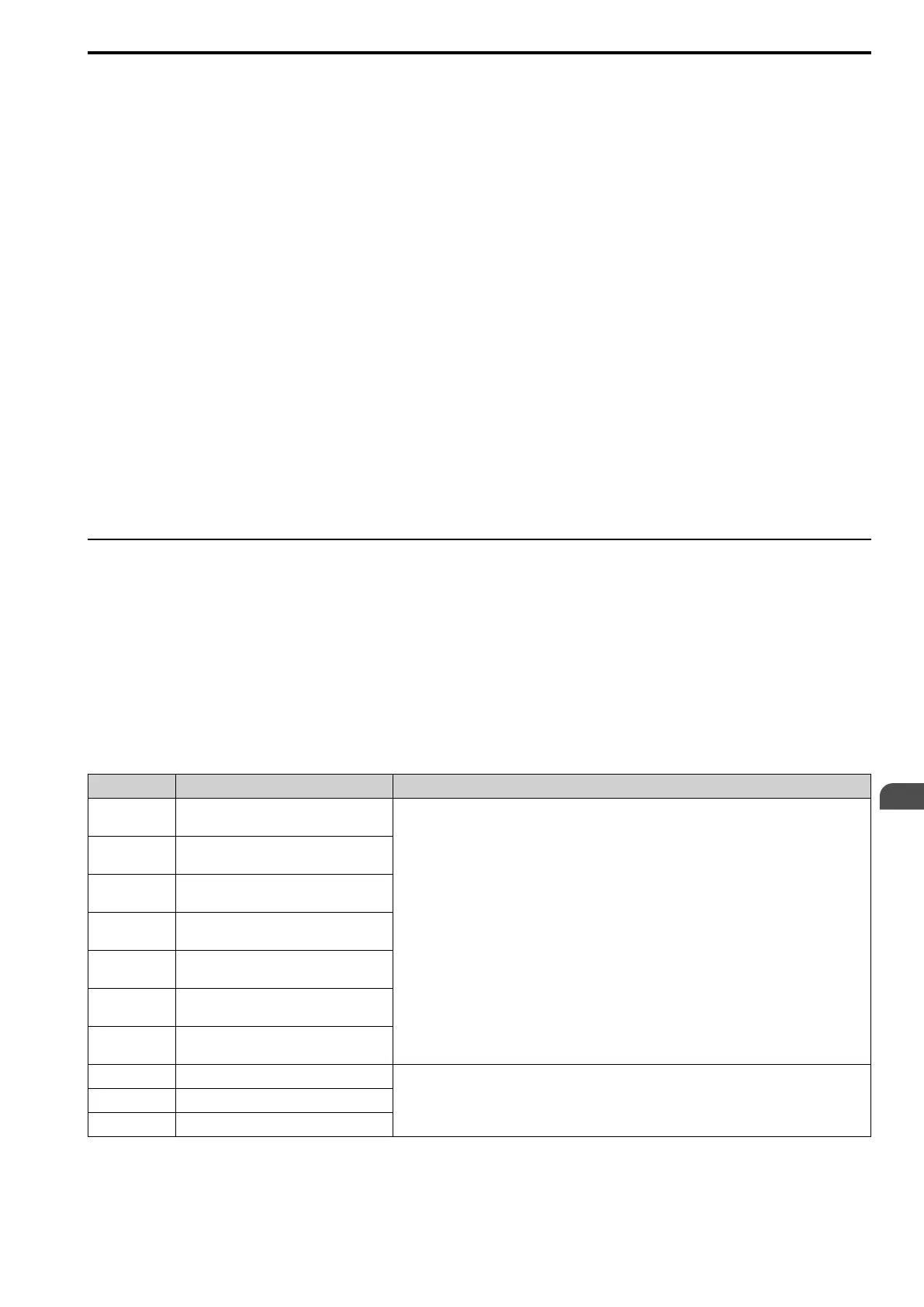
Table 3.5 Digital Inputs
Terminal Name (Default) Function (Signal Level)
DI1
MFDI selection 1
(ON: Forward run OFF: Stop)
• Photocoupler
• 24 V, 6 mA
Note:
To set the MFDI power supply (Sinking/Sourcing Mode or internal/external power supply), install wire
jumpers between terminals DIC-D24V and DIC-D0V.
• Sinking Mode: Install a jumper between terminals DIC and D24V.
NOTICE: Do not close the circuit between terminals DIC and D0V. A
closed circuit between these terminals will cause damage to the drive.
• Sourcing Mode: Install a jumper between terminals DIC and D0V.
NOTICE: Do not close the circuit between terminals DIC and D24V. A
closed circuit between these terminals will cause damage to the drive.
• External Power Supply: No jumper is necessary between terminals DIC-D0V and terminals DIC-
D24V.
DI2
MFDI selection 2
(ON: Reverse run OFF: Stop)
DI3
MFDI selection 3
(External fault (N.O.))
DI4
MFDI selection 4
(Fault reset)
DI5
MFDI selection 5
(Multi-step speed reference 1)
DI6
MFDI selection 6
(Multi-step speed reference 2)
DI7
MFDI selection 7
(Jog command)
D0V MFDI power supply 0 V
MFDI power supply, 24 V (maximum 150 mA)
NOTICE: Do not close the circuit between terminals D24V and D0V. A
closed circuit between these terminals will cause damage to the drive.
DIC MFDI selection common
D24V MFDI power supply +24 Vdc

 Loading...


