12.7 H: TERMINALS
580 SIEPCYEUOQ2V01A Q2V Technical Manual
Note:
Refer to “C5: ASR - SPEED REGULATION on page 499” for more information.
■ 46: ASR I Reset
Setting Value Function Description
46 ASR I Reset
Sets the command to reset the integral value and use PI control or P control for the speed control loop.
ON : P control
OFF : PI control
■ 60: Timer Fn Input
Setting Value Function Description
60 Timer Fn Input
Sets the command to start the timer function. Use this setting with Timer Output [H2-xx = 39].
Note:
Refer to “b4: TIMER on page 464” for more information.
■ 61: Motor 2 Select
Setting Value Function Description
61 Motor 2 Select
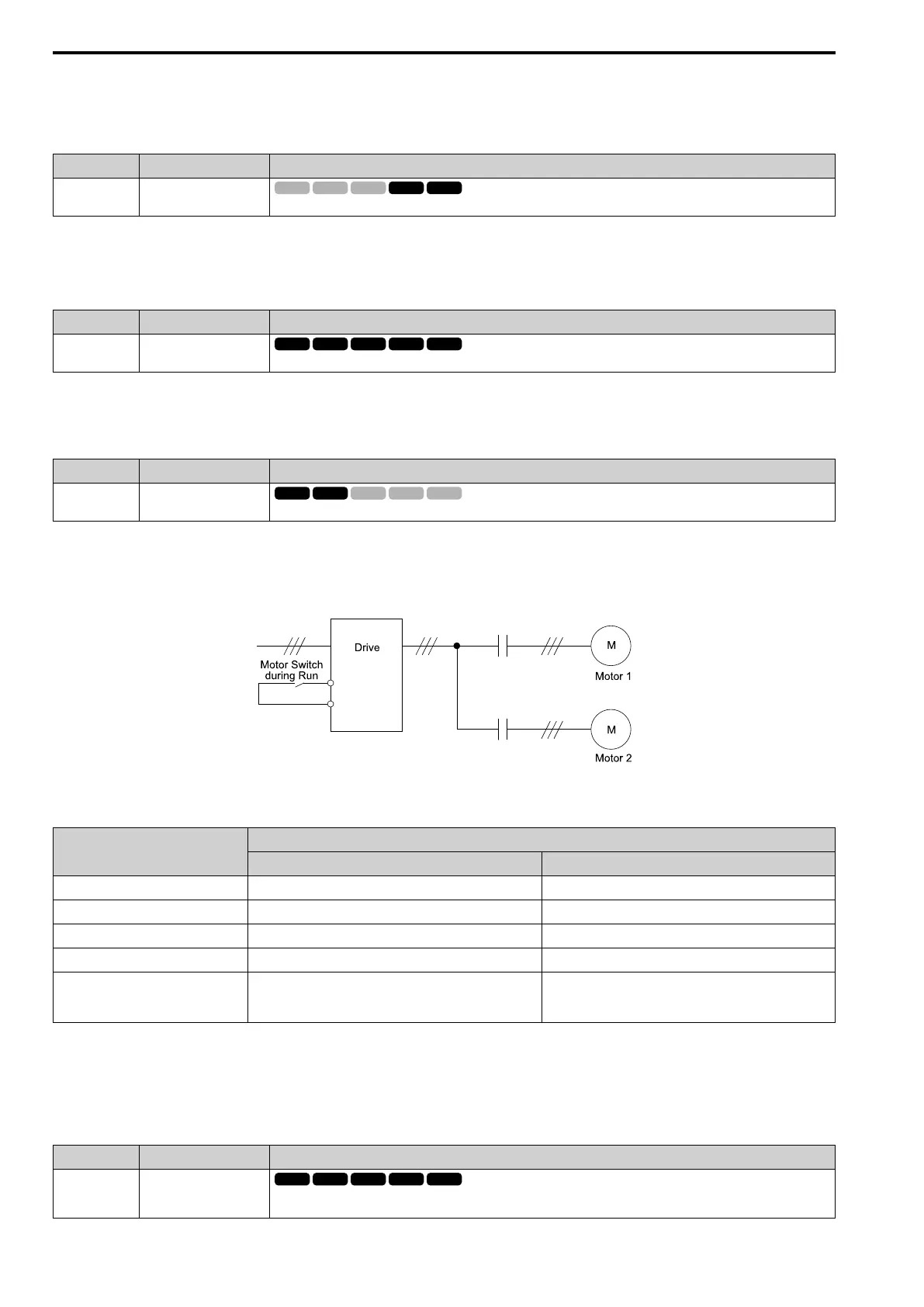
Sets the command for the drive to operate motor 1 or motor 2. Stop the motors before switching.
You can use an external input to switch operation between two induction motors. The drive will save the control
methods, V/f patterns, and motor parameters for the two motors.
ON : Operate motor 2
OFF : Operate motor 1
When you select motor 2, the drive will switch to motor 2 parameters.
Table 12.40 Parameters that Switch between Motor 1 and Motor 2
Parameter
Motor 2 Selection
OFF (Motor 1) ON (Motor 2)
C1: ACCEL / DECEL C1-01 to C1-04 C1-05 to C1-08
C3: SLIP COMPENSATION C3-01 to C3-04 C3-21 to C3-24
C4: TORQUE COMPENSATION C4-01 C4-07
C5: ASR - SPEED REGULATION C5-01 to C5-08, C5-12 -
E1: V/F PARAMETER MOTOR 1, E2:
MOTOR 1 PARAMETERS, E3: V/F
PARAMETER MOTOR 2, E4: MOTOR 2
PARAMETERS
E1-xx, E2-xx E3-xx, E4-xx
Note:
• When you use 2 motors, the drive applies the protective function set in L1-01 [Motor Cool Type for OL1 Calc] to motor 1 and motor 2.
• You cannot switch between motors 1 and 2 during run. If you try to switch motors when they are running, it will cause a rUn error.
• You must wait 200 ms minimum to input a Run command.
■ 62: Up Command
Setting Value Function Description
62 Up Command
Sets the command to use a push button switch to increase the drive frequency reference. You must also set Setting 63 [Down
Command].

 Loading...


