Parameter Details
12
12.7 H: TERMINALS
SIEPCYEUOQ2V01A Q2V Technical Manual 625
■ H6-01: PI Pulse Train Function
No.
(Hex.)
Name Description
Default
(Range)
H6-01
(042C)
PI Pulse Train Function
Sets the function for pulse train input terminal PI.
0
(0 - 3)
0 : Freq Ref
The drive inputs the frequency reference received from terminal PI when b1-01 [Freq. Ref. Sel. 1] or b1-15 = 4
[Freq. Ref. Sel. 2 = Pulse Train Input].
1 : PIDFbk Value
The drive inputs the PID control feedback value received from terminal PI.
2 : PID SP Value
The drive inputs the PID control target value received from terminal PI.
3 : PG Feedback
Select V/f Control method to enable simple encoder feedback.
Use motor speed feedback for better speed control precision. The drive compares the frequency reference to the
motor speed feedback received from the encoder, and uses the ASR function to compensates for motor slip. You
cannot use input terminal PI used for the simple encoder to detect the direction of motor rotation. Use a different
method to detect motor rotation.
Use these methods to detect the direction of motor rotation.
• Use MFDI
Set MFDI H1-xx = 15 [FWD/REV Det]. When the configured terminal is activated, the motor operates in
Reverse run. When the terminal is deactivated, the motor operates in Forward run.
Use an encoder that outputs 2-tracks (phase A, B) to detect the direction of motor rotation.
• Use the frequency reference
When the you do not use the MFDI, the Forward/Reverse run command is the same as the direction of motor
rotation.
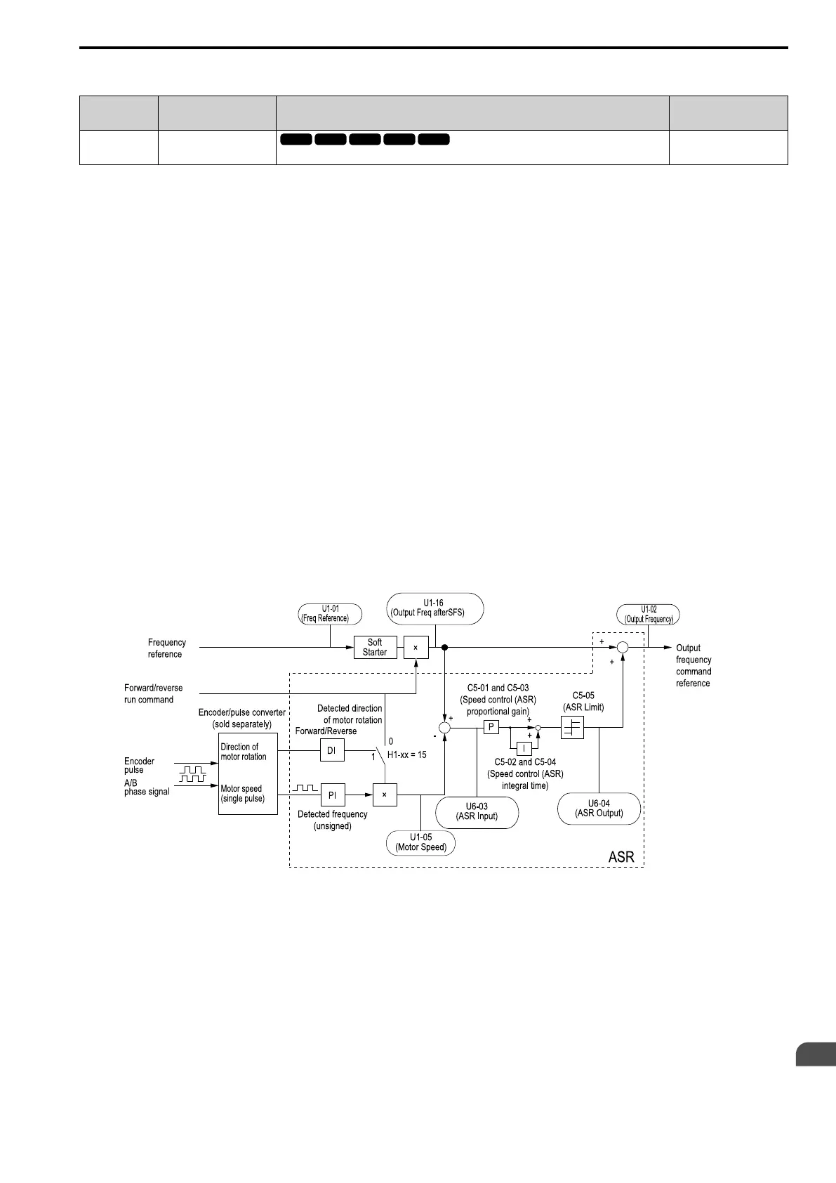
Figure 12.101 shows speed control in Simple Closed Loop V/f Mode.
Figure 12.101 Simple Closed Loop Speed Control Block Diagram
Enable Simple Closed Loop V/f Mode
1. Connect the encoder output pulse wiring to terminal PI.
2. Set A1-02 = 0 [Control Method = V/f Control].
3. Set H6-01 = 3.
4. Set H6-02 [PI Frequency Scale] to the speed feedback (pulse train input signal) frequency at the time when
the frequency reference is 100%.
Make sure that H6-04 [PI Function Bias = 0% and H6-03 [PI Function Gain] = 100%.
5. Select the detection method for the direction of motor rotation.
When you use an MFDI, set H1-xx = 15.
6. Set C5 parameters related to ASR gain and integral time to adjust responsiveness.

 Loading...


