1PPS In/Out
1PPS In/Out, Fiber
The connector number for the input is: J1
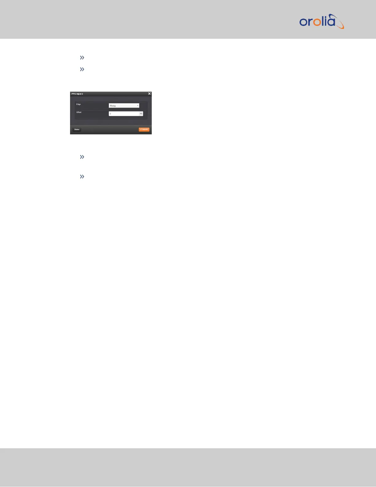
The Edit window allows the configuration of the following settings:
Edge: The operator can select either the rising or the falling edge as the input time
reference (defines the on-time point of the signal).
Offset: It is possible to add an offset to the input signal (to account for cable delays),
with a resolution of 5ns and a positive or negative value of 500ms maximum.
2.19.3 Configure an ASCIIInput
An ASCII Input is available by default configuration through the Multi-I/O connector (see
"Configurable Connectors" on page136).
To configure the ASCII Input (also referred to as ‘Reference’), go to its Edit window.
142
CHAPTER 2 • SecureSync 2400 User Manual Rev. 2
2.19 Configuring Input References