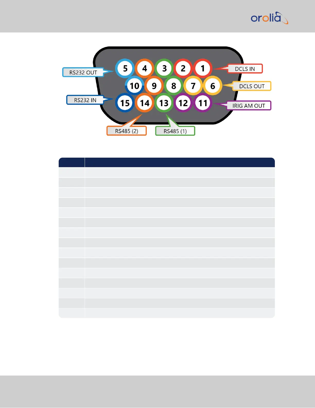
Figure 2-9: Multi I/O 15-pin connector, in mating direction from front
Pin Signal
1 DCLS IN
2 GND
3 (First signal) RS485 A, non-inverting
4 (Second signal) RS485 A, non-inverting
5 RS232 TX OUT
6 DCLS OUT
7 GND
8 GND
9 GND
10 GND
11 IRIG AM OUT
12 GND
13 (First signal) RS485 B, inverting
14 (Second signal) RS485 B, inverting
15 RS232 RX IN
2.18.3 Assigning Signals
Changing the signals on either the rear panel BNC DCLS connector, or on the Multi I/O 15-
pin connector requires access to the Web UI.
138
CHAPTER 2 • SecureSync 2400 User Manual Rev. 2
2.18 Configurable Connectors