h.
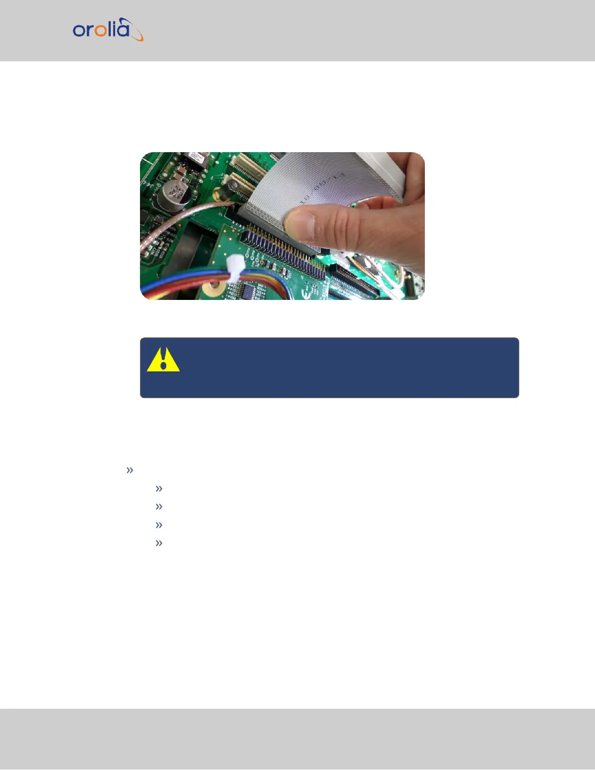
Take the supplied 50-pin ribbon cable and carefully press it into the connector on
the mainboard (lining up the red sided end of the cable with PIN 1 on the main-
board), then into the connector on the option card (see Figurebelow).
Figure 5-9: Ribbon cable installation
Caution: Ensure that the ribbon cable is aligned and fastened prop-
erly to all pins on the connector of the card. Otherwise, damage to
equipment may result during power up.
5.2.2.11 [8]: Frequency Output Cards: Wiring
Additional installation instructions for the following option card models:
Frequency Output cards:
1MHz (PN 1204-26)
5MHz (PN 1204-08)
10MHz (PN 1204-0C)
10 MHz (PN 1204-1C)
For the cable installation, follow the steps detailed below:
a.
Install the coax cable(s) onto the main PCB, connecting them to the first available
open connectors, from J4 to J7. See figure below:
SecureSync 2400 User Manual 351
APPENDIX