micro-B USB serial console
intake for temperature-controlled cooling fans
The OLED information display is configurable using the front panel controls. The micro
USB serial interface and the front panel controls provide a means to configure the unit’s
network settings and perform other functions without requiring access to the Web UI.
SecureSync units with the SAASM GPS receiver option module installed also have an
encryption key fill connector and key zeroize pin switch on the left-hand side of the front
panel.
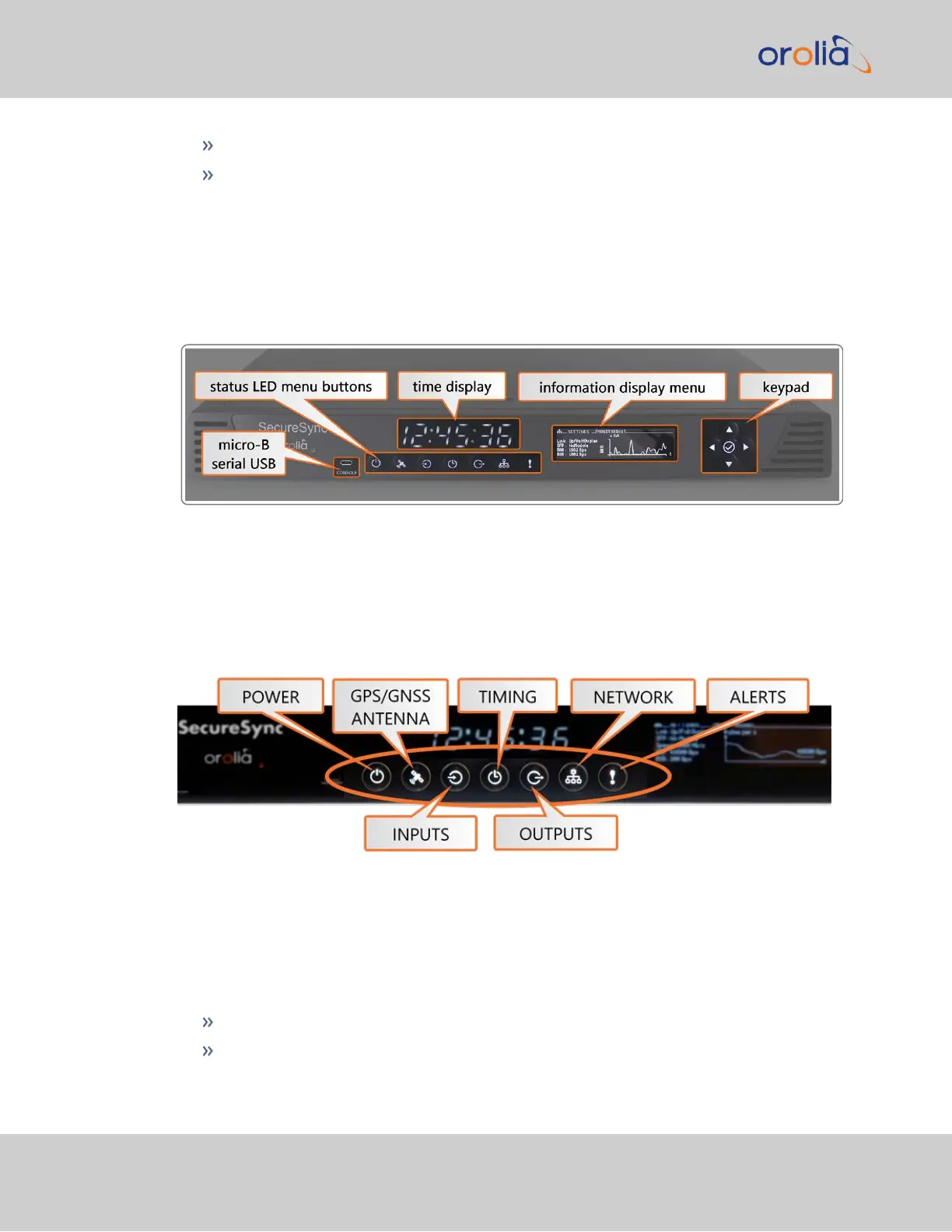
Figure 1-1: SecureSync front panel layout
1.3.1 Status LEDs
SecureSync's front panel status LEDs provide a real-time status overview: Seven (7) LEDs
indicate the unit's current operating state.
Figure 1-2: Front panel LEDs
1.3.1.1 Blinking Intervals
The status LEDs can communicate four different operating states:
"OFF"
"ON"
4
CHAPTER 1 • SecureSync 2400 User Manual Rev. 2
1.3 SecureSync Front Panel