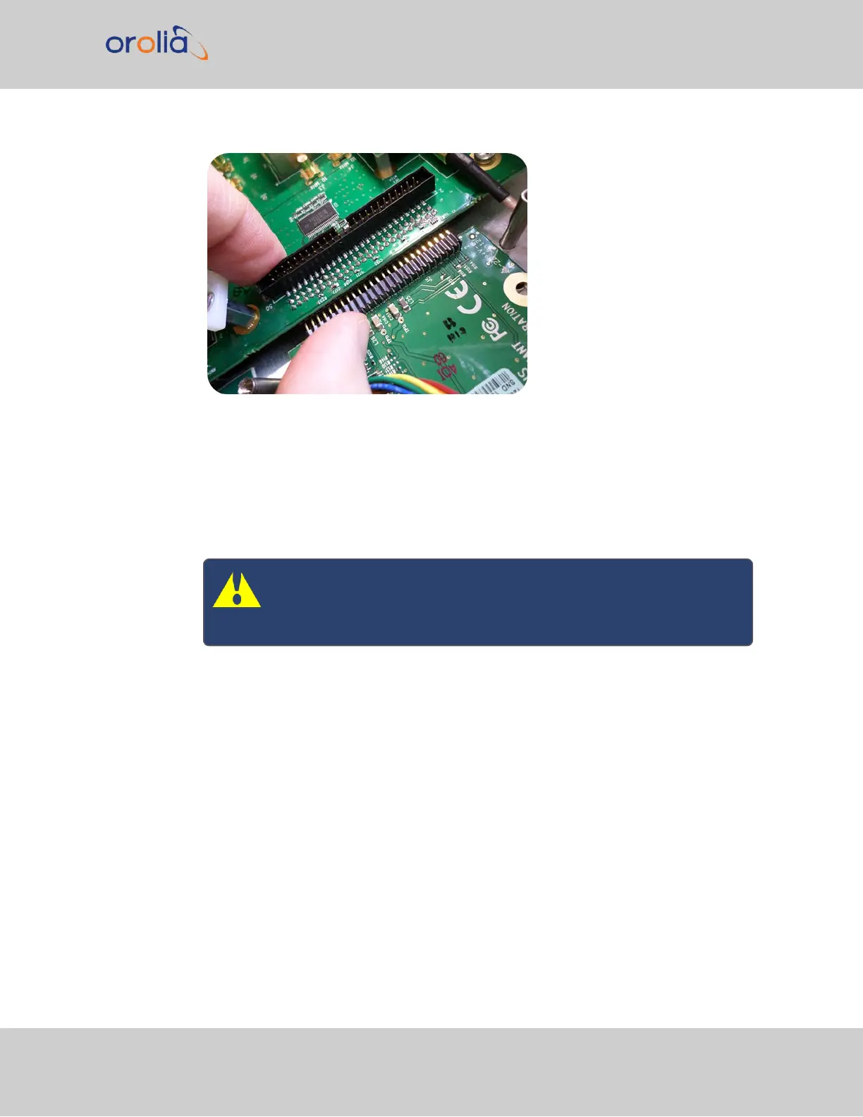
Figure 5-5: Connector installation
d.
Using the supplied M3 screws, screw the board, and the option card plate into the
chassis, applying a torque of 0.9Nm/8.9in-lbs.
If you are reinstalling an option card above this one, you can instead follow the
instructions for " [7]: Top Slot Installation, Bottom Slot Occupied" on page349
(you will be screwing on standoffs, rather than screws, in this situation).
Caution: Ensure that screw holes on the card are properly lined up
and secured to the chassis before powering the unit up, otherwise
damage to the equipment may result.
5.2.2.9 [6]: Top Slot Installation, Bottom Slot Empty
Instructions for installing an option card into an upper slot (4, or 6) of the SecureSync unit,
with no card populating the bottom slot:
a.
Safely power down your SecureSync unit and remove the top cover of the main
chassis (housing). Save the screws.
SecureSync 2400 User Manual 347
APPENDIX