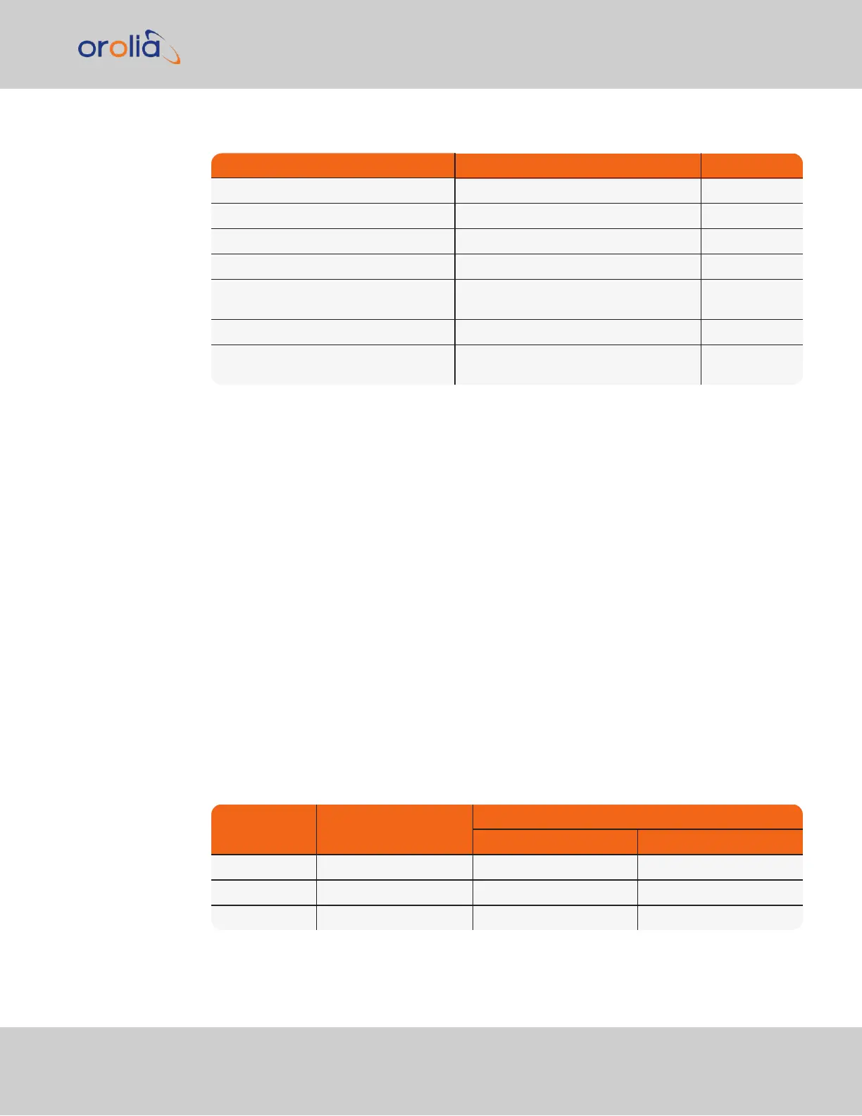
Table 1-10:
Multi I/O signal defaults
Pins Channel Default Signal
6 & 7 DCLS OUT IRIG OUT
1 & 2 DCLS IN IRIGIN
15 & 10 RS232 IN ATC IN
5 & 10 RS232 OUT ATC OUT
3, 8, 13 RS485 (1) HAVEQUICK
OUT
4, 9, 14 RS485 (2) HAVEQUICKIN
11 & 12 IRIG AM OUT IRIGOUT(AM
ONLY)
1.6.5 DCLS Output
The rear panel DCLS OUT BNC female connector defaults to a 1PPS Output (see below),
but can be configured to produce different output signals: IRIG Output, HaveQuick Output,
and GPIOOutput. For more information, see "Configurable Connectors" on page136.
1.6.5.1 1PPS Output
Signal: One pulse-per-second square wave (ext. reference connected to GNSS receiver)
Signal level: TTL compatible, 4.3 V minimum, base-to-peak into 50 Ω
Pulse width: Configurable pulse width (200 ms by default)
Pulse width range: 20 ns to 900 ms
Rise time: <10 ns
Accuracy: Positive edge within ±50 ns of UTC when locked to a valid, traceable input ref-
erence
Connector: BNC female
Table 1-11:
1PPS output accuracies
Oscillator Type
Accuracy to UTC
(1 sigma locked to GPS)
Holdover (constant temp. after 2weeks of GPS lock)
After 4 hours After 24 hours
Rubidium ±25 ns 0.2 μs 1μs
OCXO ±50 ns 1μs 25 μs
TCXO ±50 ns 12 μs 450 μs
1.6 Specifications
CHAPTER 1 • SecureSync 2400 User Manual Rev. 2
27