Figure 5-6: Washers & standoffs secured to chassis screw holes
d.
Insert option card into the slot, lining up the screw holes on the card with the stan-
doffs.
e.
Using the supplied M3 screws, screw the board into the standoffs, and the option
card plate into the chassis, applying a torque of 0.9Nm/8.9in-lbs.
f.
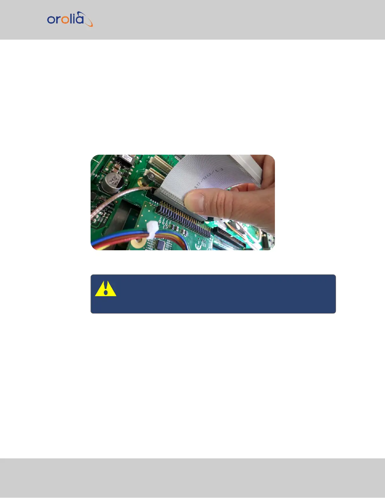
Take the supplied 50-pin ribbon cable and carefully press it into the connector on
the mainboard (lining up the red sided end of the cable with PIN 1 on the main-
board), then into the connector on the option card (see Figurebelow).
Figure 5-7: Ribbon cable installation
Caution: Ensure that the ribbon cable is aligned and fastened prop-
erly to all pins on the connector of the card. Otherwise, damage to
the equipment may occur during power-up.
5.2.2.10 [7]: Top Slot Installation, Bottom Slot Occupied
Instructions for installing an option card into an upper slot (4, or 6), above a populated bot-
tom slot:
a.
Safely power down the SecureSync unit, and remove the top cover of the main
chassis (housing). Save the screws.
SecureSync 2400 User Manual 349
APPENDIX