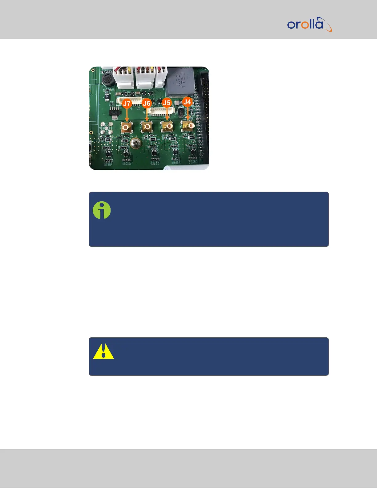
Figure 5-10: J Connectors
Note: For 10MHz option cards with 3 coax cables: From the rear of
the option card, outputs are labeled J1, J2, J3. Start by connecting
the cable attached to J1 on the card to the first available open con-
nector on the SecureSync mainboard, then connect the cable
attached to J2, then J3, etc.
b.
Using the supplied cable ties, secure the coax cable from the option card to the
white nylon cable tie holders fastened to the mainboard.
5.2.2.12 [9]: Verifying HW Detection and SW Update
Complete the Option Card installation procedure by verifying that SecureSync detected
the card, and by updating the system software:
a.
Re-install the top cover of the unit chassis (housing), using the saved screws.
Caution: Ensure that screw holes on the card are properly lined up
and secured to the chassis before powering the unit up, otherwise
damage to the equipment may result.
352 SecureSync 2400 User Manual
APPENDIX