EasyManuals Logo

Orolia SecureSync 2400 User Manual

Default Icon
589 pages
To Next Page IconTo Next Page
To Previous Page IconTo Previous Page
Page #42 background imageLoading...
Page #42 background image
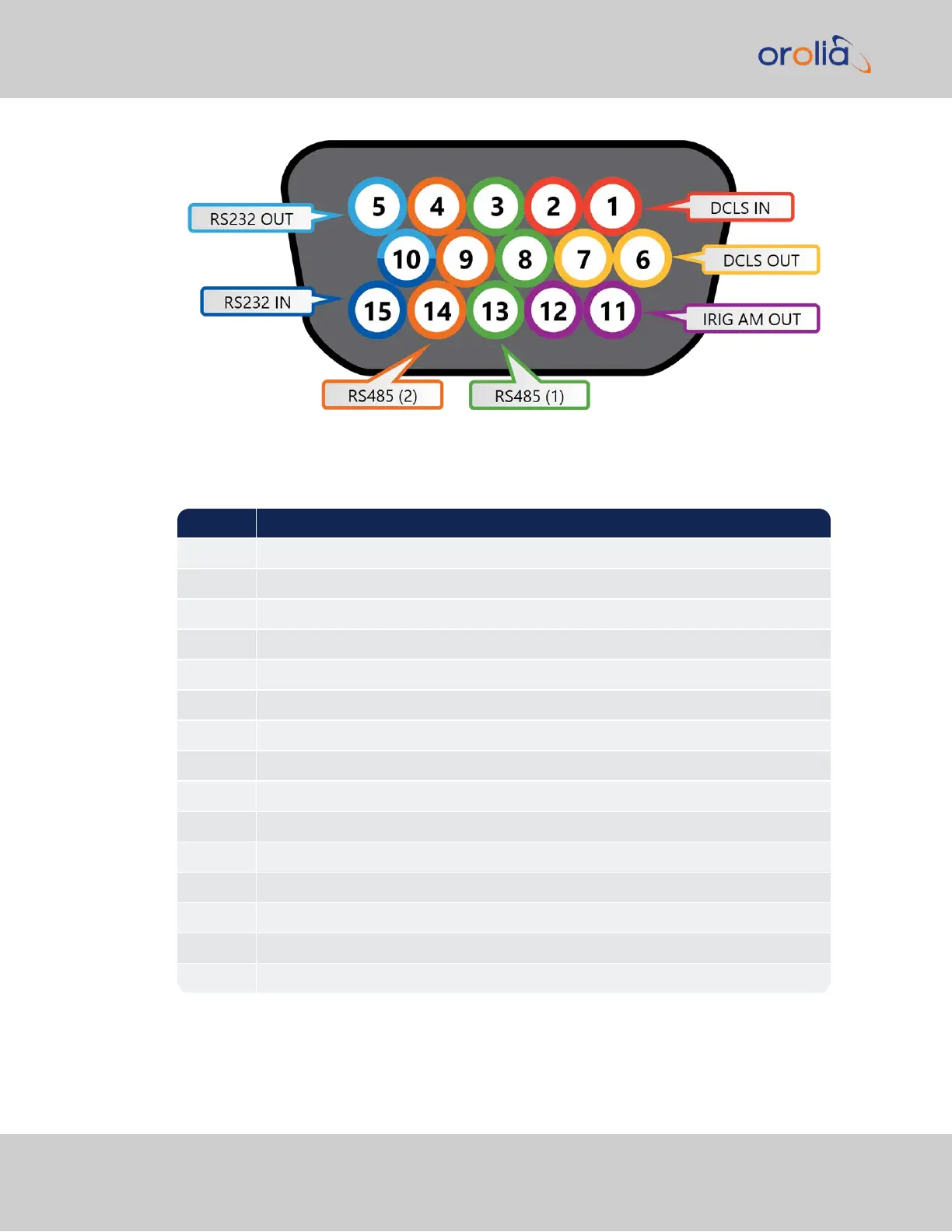
Figure 1-6: Multi I/O connector, viewed in mating direction on front of unit
Table 1-9:
Multi I/O connector signal pinout
Pin Signal
1 DCLS IN
2 GND
3 (First signal) RS485 A, non-inverting
4 (Second signal) RS485 A, non-inverting
5 RS232 TX OUT
6 DCLS OUT
7 GND
8 GND
9 GND
10 GND
11 IRIG AM OUT
12 GND
13 (First signal) RS485 B, inverting
14 (Second signal) RS485 B, inverting
15 RS232 RX IN
26
CHAPTER 1 SecureSync 2400 User Manual Rev. 2
1.6 Specifications

Table of Contents

Other manuals for Orolia SecureSync 2400

Questions and Answers:

Question and Answer IconNeed help?

Do you have a question about the Orolia SecureSync 2400 and is the answer not in the manual?

Orolia SecureSync 2400 Specifications

General IconGeneral
BrandOrolia
ModelSecureSync 2400
CategoryRecording Equipment
LanguageEnglish