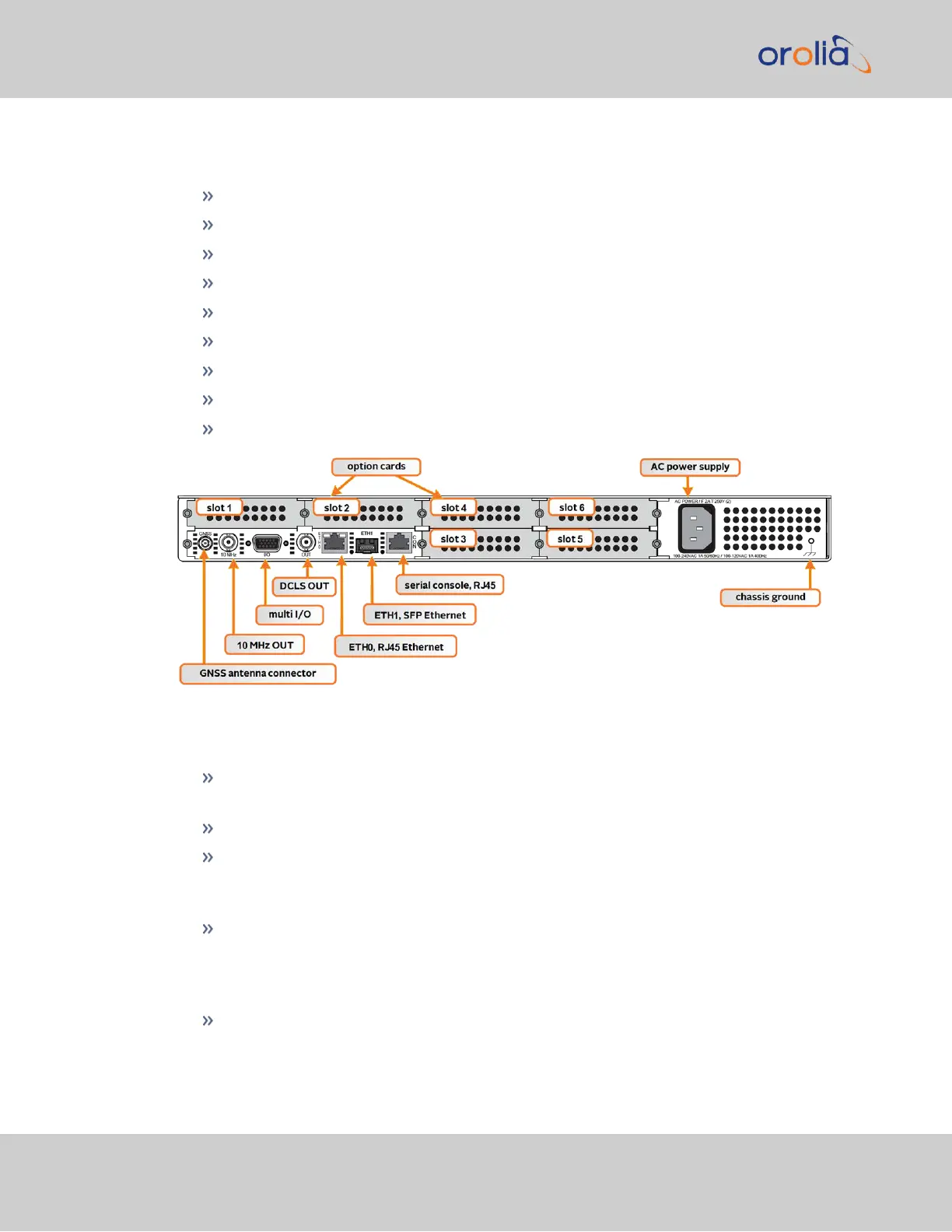
The SecureSync rear panel accommodates the connectors for all input and output ref-
erences.
GPS/GNSS antenna connector (SMA)
10 MHzoutput (BNC female connector)
Multi I/O (sub HD15 connector)
1PPS out, configurable DCLS Output (BNC female connector)
ETH0 1GB Ethernet (RJ45 connector)
ETH1 Ethernet (SFP connector)
Serial console (RJ45 connector)
Two or six slots for option cards
AC power input connection
Figure 1-4: Standard rear panel
Optional input/output connectors depend on the installed option cards.
The ANTENNA connector is an SMA connector for the GNSS input from your GNSS
antenna via a coax cable.
The 10 MHz BNC connector provides a 10 MHz sine-wave output signal.
The HD15 multi I/O connector provides 6 different configurable channels. These
channels can be set to provide various outputs and inputs, such as 1PPS, HaveQuick,
IRIG, ATC, and GPIO.
The DCLS OUT BNC connector can be set to produce 1PPS, IRIG output,
HaveQuick output, or GPIOoutput. The default 1PPS signal offers a once-per-
second square wave output signal, and can be configured to have either its rising or
falling edge to coincide with the system’s on-time point.
The Ethernet RJ45 (Eth0) and SFP (Eth1) connectors provide an interface to the
network for NTP synchronization and to obtain access to the SecureSync product
12
CHAPTER 1 • SecureSync 2400 User Manual Rev. 2
1.4 Unit Rear Panel