corresponding lower slot (3 or 5) is occupied.
Slots 1 and 2 always have an occupied slot below them.
Units must be equipped with an Extension Board to fill option card slots 3, 4,
5, and 6.
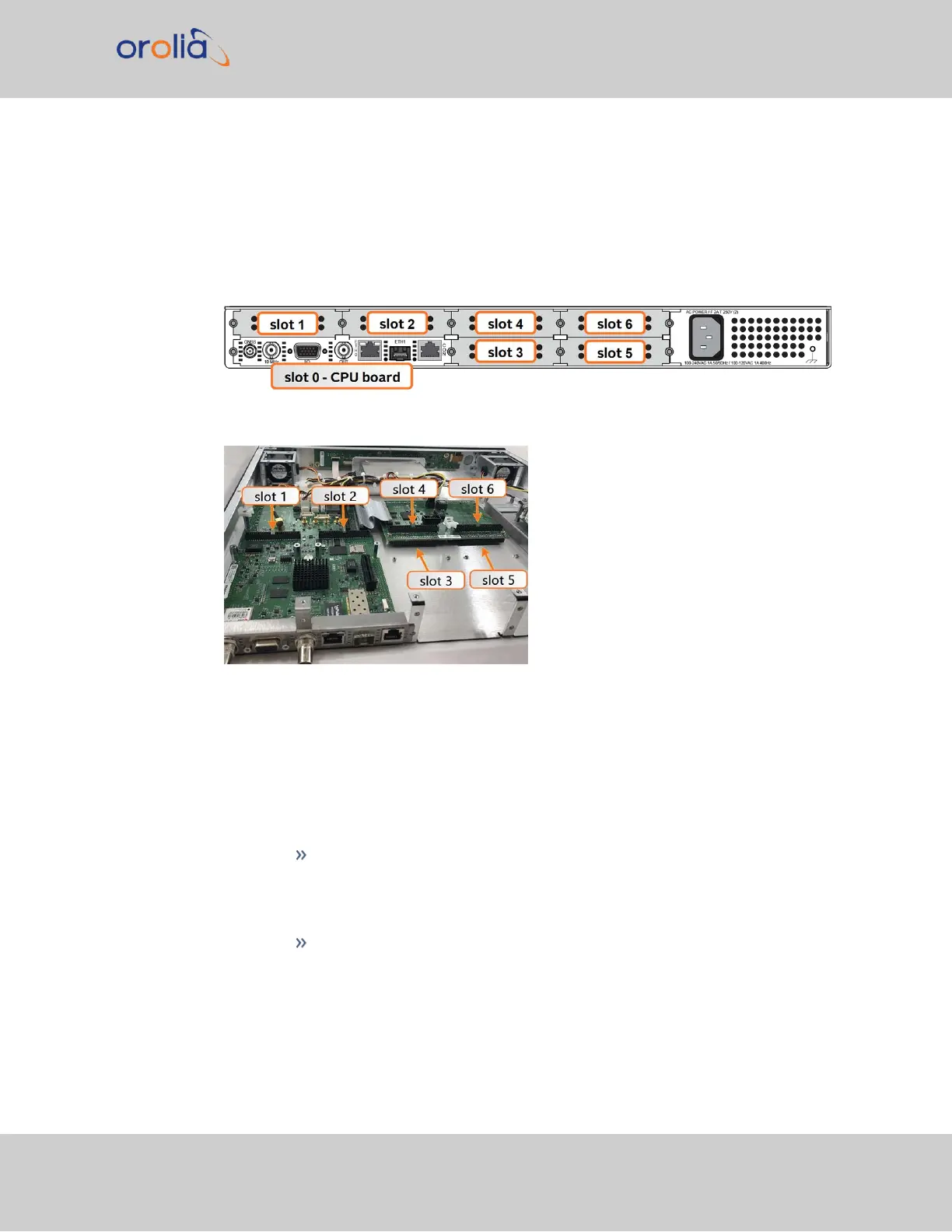
Figure 5-2: Unit rear view
Figure 5-3: Unit internal view (from rear)
c.
Identify your installation steps.
i.
All installation situations include steps 1 (unpacking), 2 (save reference con-
figuration), and 3 (determine installation procedure).
ii.
Steps 4 through 8 of this installation procedure should only be performed if
your installation location or card requires it:
Step 4
is for installation in slots 1 or 2
("[4]: Slot 1 & 2 Installation" on the next page)
Step 5
should be followed for bottom card installation in slots 3 and 5
SecureSync 2400 User Manual 343
APPENDIX