Table 5-15:
Accepted IRIG reference formats
IRIG Output: Signal State
To quickly view if an IRIG output is enabled, or disabled, navigate to the option card’s
Status Summary panel. For instructions, see: "Viewing an Input/Output Signal State" on
page337.
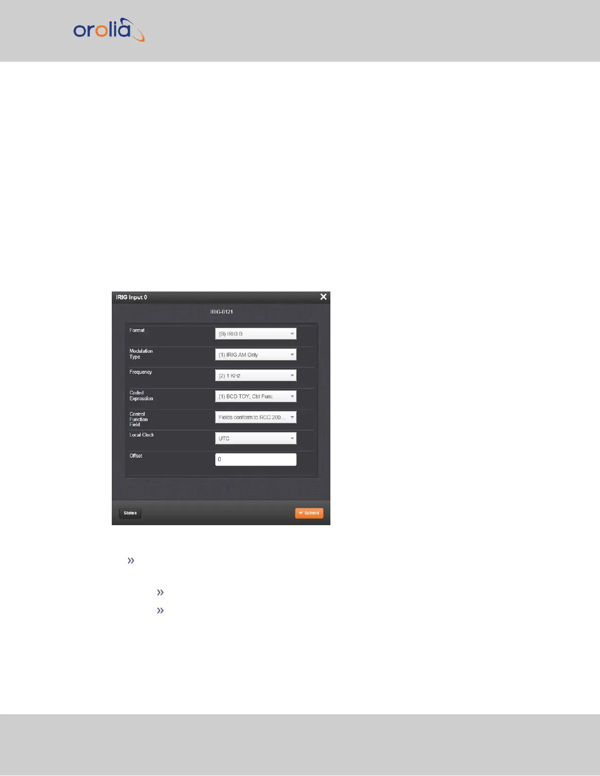
IRIG Input: Edit Window
To configure the IRIG Input (also referred to as ‘Reference’), navigate to its Edit window.
For instructions, see: "Configuring Option Card Inputs/Outputs" on page336.
The Web UI list entries for these cards are: IRIG In/Out BNC and IRIG In/Out Fiber.
The connector number is: J1.
The Edit window allows the configuration of the following settings:
Format: Sets the formatting of the IRIG input signal, as defined by the IRIG gen-
erator time source. The available choices are:
IRIG A
IRIG B
SecureSync 2400 User Manual 409
APPENDIX