The Web UI list entries for these cards are: IRIG In/Out BNC and IRIG In/Out Fiber. The
connector numbers are: J2 and J3.
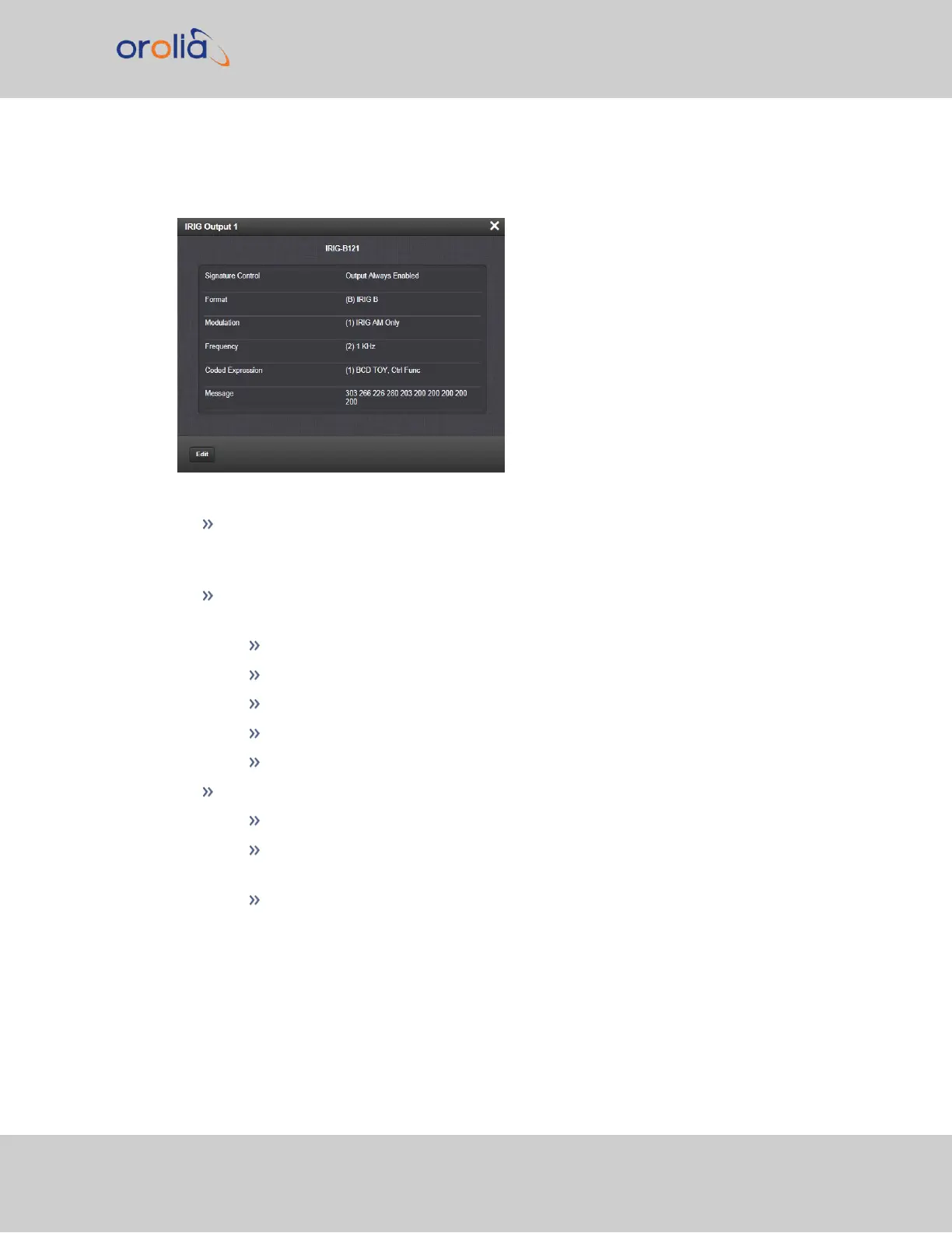
The Status window displays the following settings:
Signature Control: is used to control when the IRIG modulation will be present.
This function allows the modulation to stop under certain conditions;see also "Sig-
nature Control" on page161.
Format: Used to configure the desired IRIG output formatting. The possible values
are:
IRIG A
IRIG B
IRIG G
IRIG E
NASA-36
Modulation: Changes the type of output signal modulation. The possible values are:
IRIG DCLS—A TTL-modulated output.
IRIG AM-–An amplitude modulated output. The amplitude of the output is
determined by the value entered in the Amplitude field.
Frequency—The IRIG modulation frequency. This is determined by the con-
figuration of Format and Modulation Type. See also: "IRIG Carrier Fre-
quencies" on page546.
SecureSync 2400 User Manual 417
APPENDIX