Pin No. Signal Function Pin No. Signal Function
10 TFD Time Fault Discrete 23 GND Ground
11 TOD1 TOD1 TTL Out 24 1PPS 1PPS TTL Out
12 GND Ground 25 GND Ground
13 TOD2 TOD2 TTL Out
Table 5-16:
Models 1204-11, -25: DB-25 pin-out
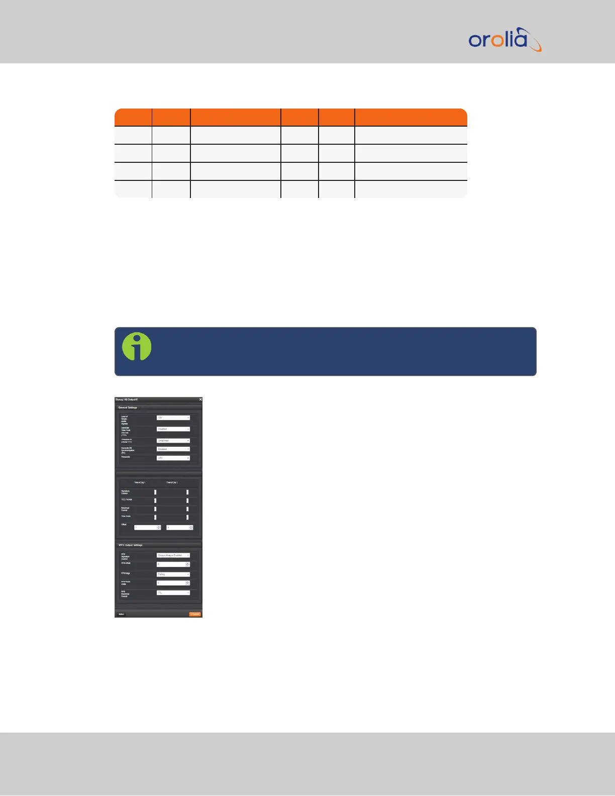
STANAG Output: Edit Window
To configure a STANAG output, go to its Edit window. For instructions, see: "Configuring
Option Card Inputs/Outputs" on page336.
The Web UI list entries for these cards are: STANAG Out and STANAG Out, Isolated.
The outputs are named: Stanag HQ Output [number].
Note: SecureSync starts numbering I/O ports with 0 (only 1PPS and
10MHz outputs start at1, because of the built-in outputs).
The Edit window allows the configuration of the following settings:
420 SecureSync 2400 User Manual
APPENDIX