Caster Table Type M34 (D3EP-03)
D0AP/D0C4/D0C5/D0C6/M0BQ/M0D1 2-38 SM
2.7 CASTER TABLE TYPE M34 (D3EP-03)
When installing two or more optional trays on the caster table, it is required to install by the
customer engineer.
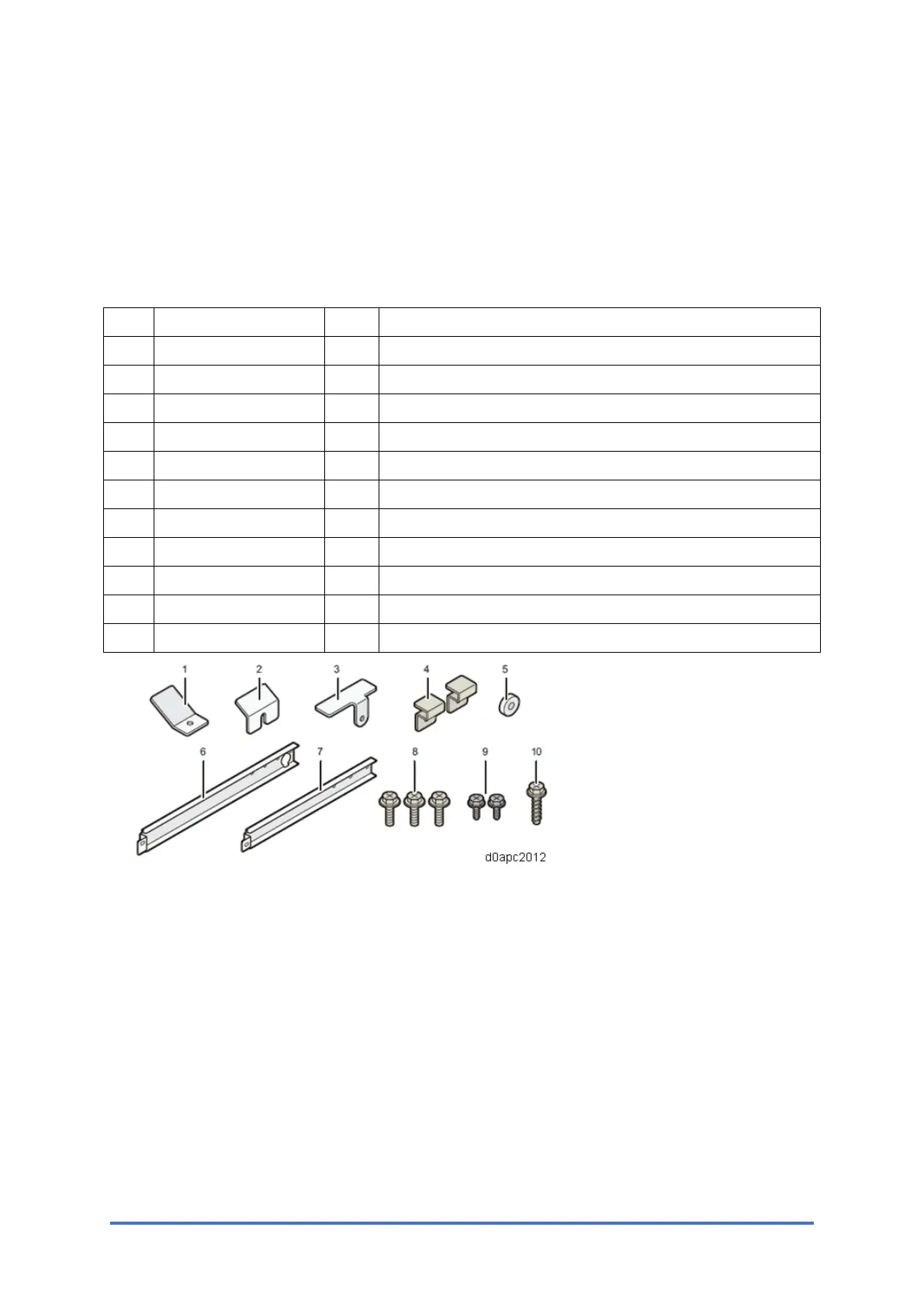
2.7.1 ACCESSORIES
No. Description Q'ty Installation location
1 Plate A-1 1 Caster table - Paper feed unit (Front right)
2 Plate A-2 1 Caster table - Paper feed unit (Front left)
3 Plate B-1 1 Main machine - Paper feed unit (Rear left)
4 Plate B-2 2 Paper feed unit - Paper feed unit (Rear)
5 Spacer 1 Caster table - Paper feed unit (Rear right)
6 Plate C-1 1 Caster table - Paper feed unit (Rear right)
7 Plate C-2 1 Only used when installing three paper feed units.
8 Screw A (M4×8) 3 Caster table - Paper feed unit
9 Screw B (M3×6) 2 Paper feed unit, Main machine (Left side)
10 Screw C (M3x12) 1 Paper feed unit, Main machine (Right side)
- Installation Guide 1 -
2.7.2 INSTALLATION PROCEDURE
Refer to "Caster Table Type M34 Installation Guide" provided with the Caster Table.