Minimum cable cross-section: 4mm
2
(AWG10)
PE terminal tightening torque: 1.5Nm (13.3lbf.in)
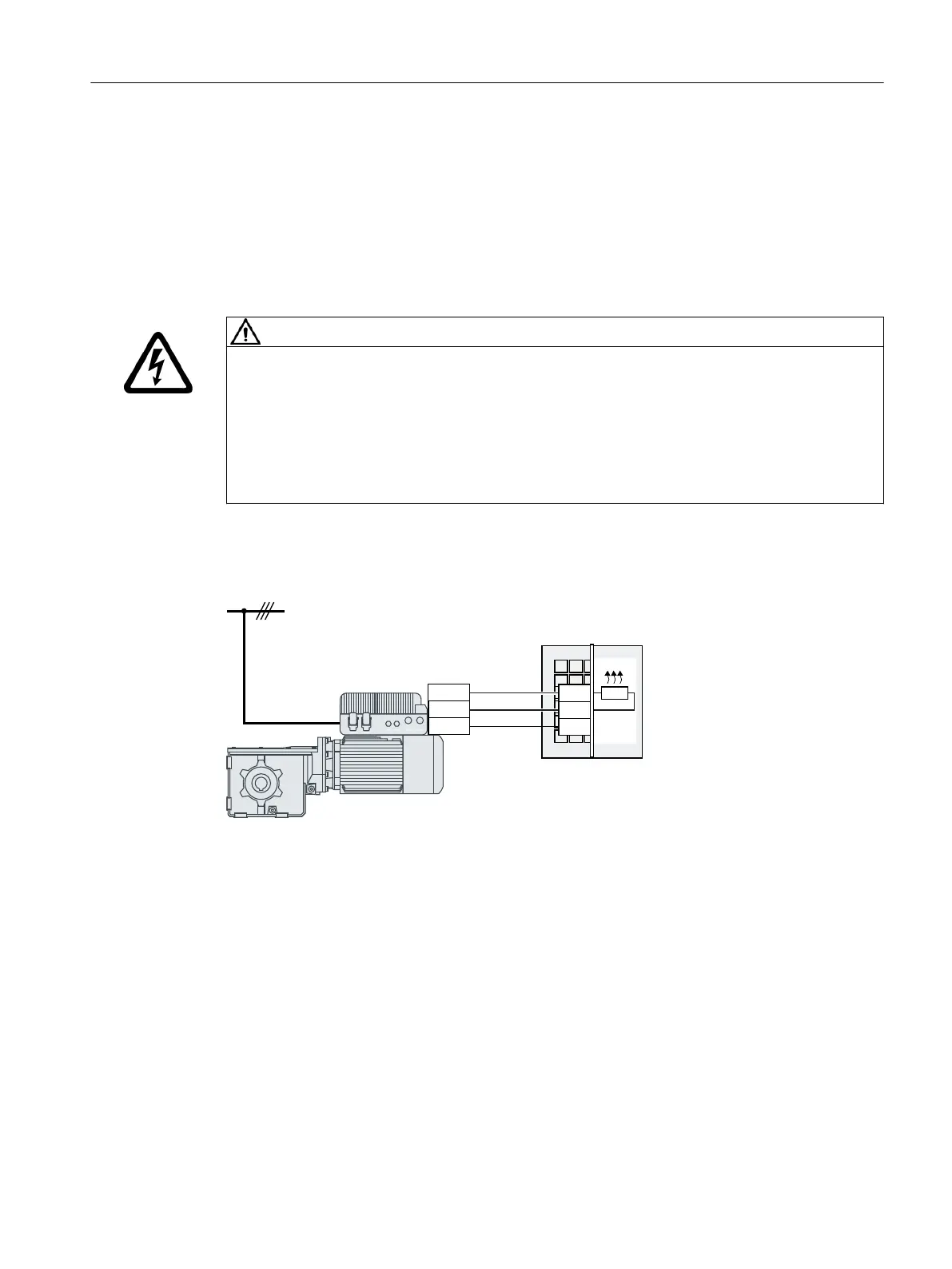
5.17 Connecting the external braking resistor
WARNING
Electric shock as a result of a residual charge in power components
After the power supply has been switched o, it takes up to 5 minutes until the capacitors in the
converter have discharged so that the residual charge is at a non-hazardous level. Therefore,
touching the converter immediately after powering o can result in electric shock due to
residual charge in the power components.
• Check the voltage at the converter connections before you connect the external braking
resistor.
Connection overview
1#
%$1
3
1&
1&
3
(%
#SBLJOHSFTJTUPS
Procedure
1. Switch o all power supplies (line supply and external 24 V power supply) to the converter.
2. Wait 5 minutes to allow the converter to discharge and check that no voltage is present at the
converter connections.
3. Release the retaining screws (6 x M4) on the Electronic Module by using a 3 mm allen key, and
remove the module.
Wiring
5.17Connecting the external braking resistor
SINAMICS G115D Wall Mounted distributed drive
Operating Instructions, 07/2023, FW V4.7 SP14, A5E52808211A AA 101

 Loading...


