3.4.3 Glanded installation kit
Glanded installation kit for G115D Motor Mounted
Article number Illustration Interface Cable
gland
Quanti‐
ty
Tightening
torque
6SL3566-2GM00-0GA0 Line supply - X1/X3 M25 × 1.5 2 12Nm
(106.2lbf.in)
24 V power supply - X01/X02 M20 × 1.5 2 12Nm
(106.2lbf.in)
Digital inputs/outputs -
X07/X08/X05
M16 × 1.5 3 10Nm
(88.5lbf.in)
Glanded installation kit for G115D Wall Mounted
Article number Illustration Interface Cable
gland
Quanti‐
ty
Tightening
torque
6SL3566-2GW00-0GA0 Line supply - X1/X3 M25 × 1.5 2 12Nm
(106.2lbf.in)
Motor - X2 M25 × 1.5 1 12Nm
(106.2lbf.in)
24 V power supply - X01/X02 M20 × 1.5 2 12Nm
(106.2lbf.in)
Digital inputs/outputs -
X07/X08/X05
M16 × 1.5 3 10Nm
(88.5lbf.in)
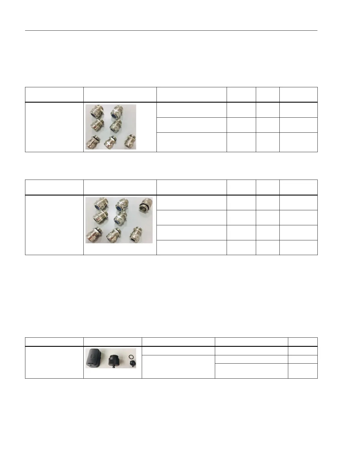
3.4.4 Connector cover kit
Connector cover kit for G115D converter with daisy chain
For the connector variant of the G115D converter with daisy chain, if you don’t use daisy chain
connection, cover the unused connectors with the optional connector cover kit to maintain the
IP rating of the system.
Article number Illustration Interface Connector caps Quantity
6SL3566-2GA00-0GA0 Line supply (OUT) - X3 Q4/2 connector sealing cap 1
24 V power supply (OUT) -
X02
7/8" connector sealing cap 1
M12 L-code connector sealing
cap
1
Overview of the SINAMICS G115D drive
3.4Optional components
SINAMICS G115D Wall Mounted distributed drive
36 Operating Instructions, 07/2023, FW V4.7 SP14, A5E52808211A AA

 Loading...


