Commands for switching the motor on and o
ON
JOG 1
JOG 2
Enable operation
The converter switches the motor on.
OFF1, OFF3 The converter brakes the motor. The converter switches o the motor once it comes to a standstill.
The motor is considered to be stationary if the speed is less than a dened minimum speed.
OFF2
Inhibit operation
The converter switches o the motor immediately without rst braking it.
Further information
You will nd additional information in function diagram 2610 of the List Manual.
7.3 Adapt the default settings of the inputs and outputs
7.3.1 Overview
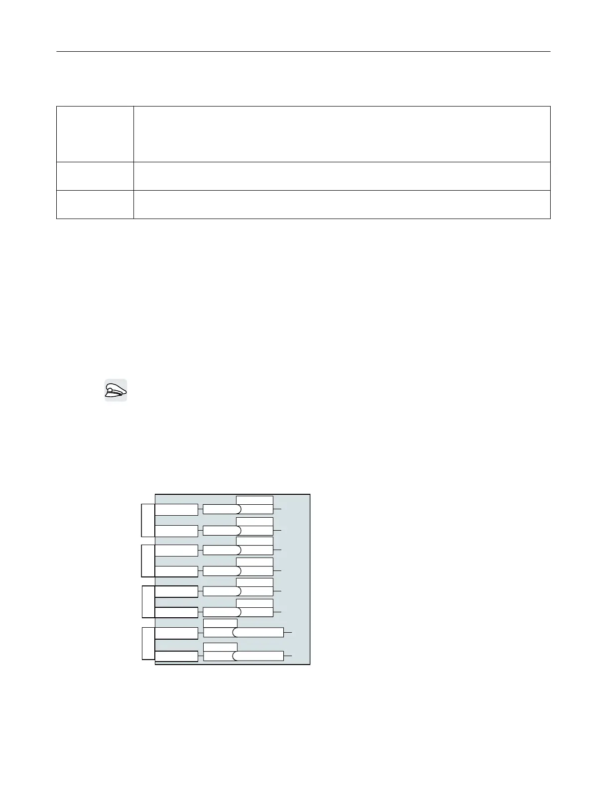
In the converter, the input and output signals are interconnected with specic converter
functions using special parameters. The following parameters are available to interconnect
signals:
• Binectors BI and BO are parameters to interconnect binary signals.
• Connectors CI and CO are parameters to interconnect analog signals.
This chapter describes how you adapt the function of individual converter inputs and outputs
using binectors and connectors.
;;
',
',
',
',
U
U
U
U
%,S[[[[
%,S[[[[
%,S[[[[
%,S[[[[
;
',2
',2
;
',2
',2
U
U
%,S[[[[
%,S[[[[
S
S
%2U\\[[Q
%2U\\[[Q
1)
If parameterized as digital inputs via p0728
2)
If parameterized as digital outputs via p0728
Advanced commissioning
7.3Adapt the default settings of the inputs and outputs
SINAMICS G115D Wall Mounted distributed drive
Operating Instructions, 07/2023, FW V4.7 SP14, A5E52808211A AA 133

 Loading...


