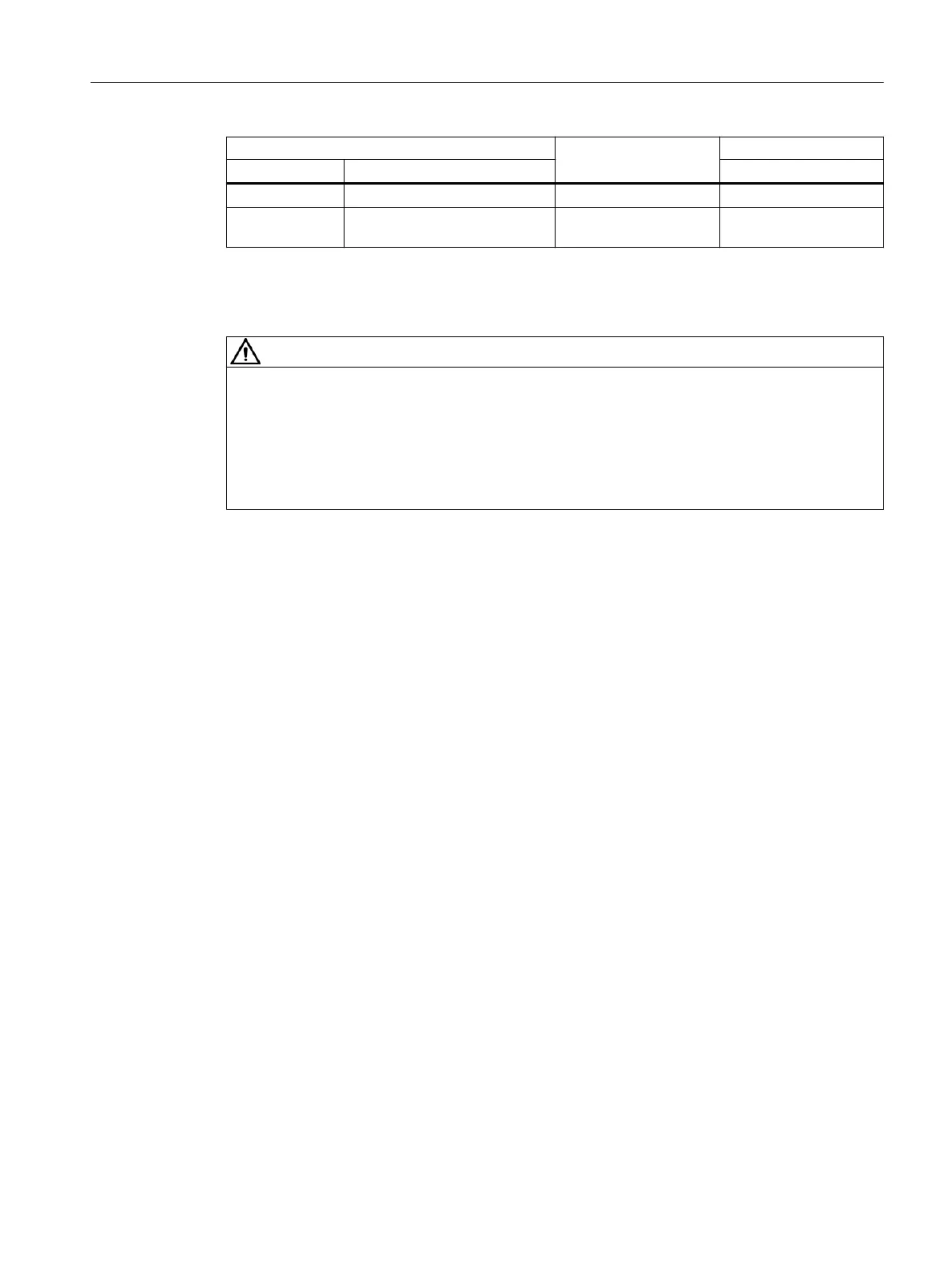
Brake type Thread size Tightening torque
Siemens Brake supplier Nm
L32 INTORQBABFK458(12E) 3xM6 10
L60, L80 INTORQBABFK458(14E), IN‐
TORQBABFK458(16E)
3xM8 25
12.2.20.4 Replacing the friction lining
WARNING
Unintentional starting of the drive unit
Switch o the power supply to the drive unit.
The brake must be in a torque-free condition.
Secure the drive unit to prevent it from being started up unintentionally.
Attach a warning notice to the start switch.
Procedure
1. Remove the fan cover.
When combined with manual release:
Unscrew the manual brake release lever.
2. Release the connecting cable.
3. Remove the fan locking ring and pull out the fan.
4. Loosen the brake screws evenly and remove the screws completely. Adjust the solenoid, see .
5. Completely pull the rotor o the hub.
6. Check the hub teeth.
7. Check the friction surface at the bearing shield. If there is severe scoring on the friction plate
or ange, replace the friction plate or ange. Rework the friction surfaces if there is severe
scoring on the bearing shield.
8. Measure the thickness of the new rotor and the head height of the sleeve screws with a
caliper gauge.
9. Calculate the gap between the solenoid and the armature disk as follows:
gap=rotor thickness+s
LN
-head height.
10.Unscrew the sleeve screws evenly until the calculated gap between the solenoid and the
armature disk is reached.
11.Mount the new rotor and solenoid. Set the air gap of the brake, see Adjusting the air gap
(Page469).
12.Connect the connection cable.
13.Mount the fan cover.
Additional information on the SIMOGEAR geared motor
12.2Specic data motor
SINAMICS G115D Wall Mounted distributed drive
Operating Instructions, 07/2023, FW V4.7 SP14, A5E52808211A AA 471

 Loading...


