9.2 System runtime
By evaluating the system runtime of the converter, you can decide whether you must replace
components subject to wear such as fans, motors and gear units.
Principle of operation
The converter starts the system runtime as soon as the converter is supplied with power. The
system runtime stops when the converter is switched o.
The system runtime comprises r2114[0] (milliseconds) and r2114[1] (days):
System runtime = r2114[1] × days + r2114[0] × milliseconds
If r2114[0] has reached a value of 86,400,000 ms (24 hours), the converter sets the value of
r2114[0] to 0 and increases the value of r2114[1] by 1.
Using system runtime, you can track the chronological sequence of faults and alarms over
time. When a corresponding message is triggered, the converter transfers the parameter
values r2114 to the corresponding parameters of the alarm or fault buer.
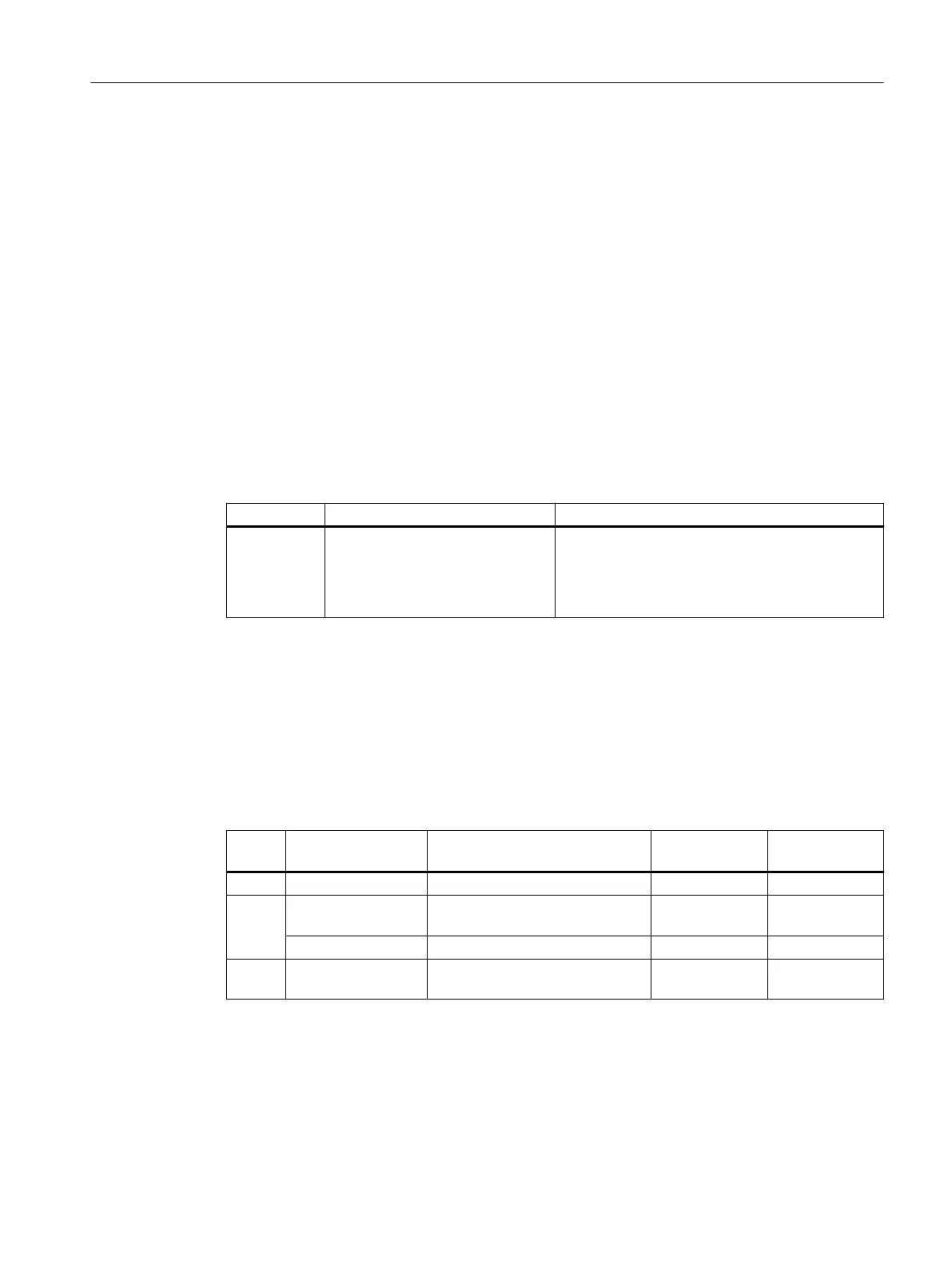
Parameter Description Setting
r2114[0...1] Total system runtime Displays the total system runtime for the drive unit.
Index:
[0]: Milliseconds
[1]: Days
You cannot reset the system runtime.
9.3 Identication & maintenance data (I&M)
I&M data
The converter supports the following identication and maintenance (I&M) data.
I&M
data
Format Explanation Associated pa‐
rameters
Example for
the content
I&M0 u8[54] PROFINET Converter-specic data, read only - See below
I&M1 Visible String [32] Plant/system identier p8806[0…31] "ak12-
ne.bo2=fu1"
Visible String [22] Location code p8806[32 … 53] "sc2+or45"
I&M2 Visible String [16] Date p8807[0…15] "2013-01-21
16:15"
Alarms, faults and system messages
9.3Identication & maintenance data (I&M)
SINAMICS G115D Wall Mounted distributed drive
Operating Instructions, 07/2023, FW V4.7 SP14, A5E52808211A AA 373

 Loading...


