Procedure
1. Push the shrink disk ③ onto the hollow shaft ②.
– 3‑part shrink disk up to the end stop for sizes19‑69.
– 2‑part shrink disk ush with the shaft end for sizes79‑109.
2. Tighten the clamping bolts ⑥, initially by hand. Align the shrink disk ③ so that the clamping
anges are plane-parallel with one other.
3. Use the torque wrench to turn each of the clamping bolts ⑥ equally by 1/6 revolution (not
crosswise); repeat this procedure several times. Observe the tightening torque.
4. Attach the rubber cover or protection cover included in the scope of supply using Removing
and installing the protection cover (Page490).
You have now installed the shrink disk.
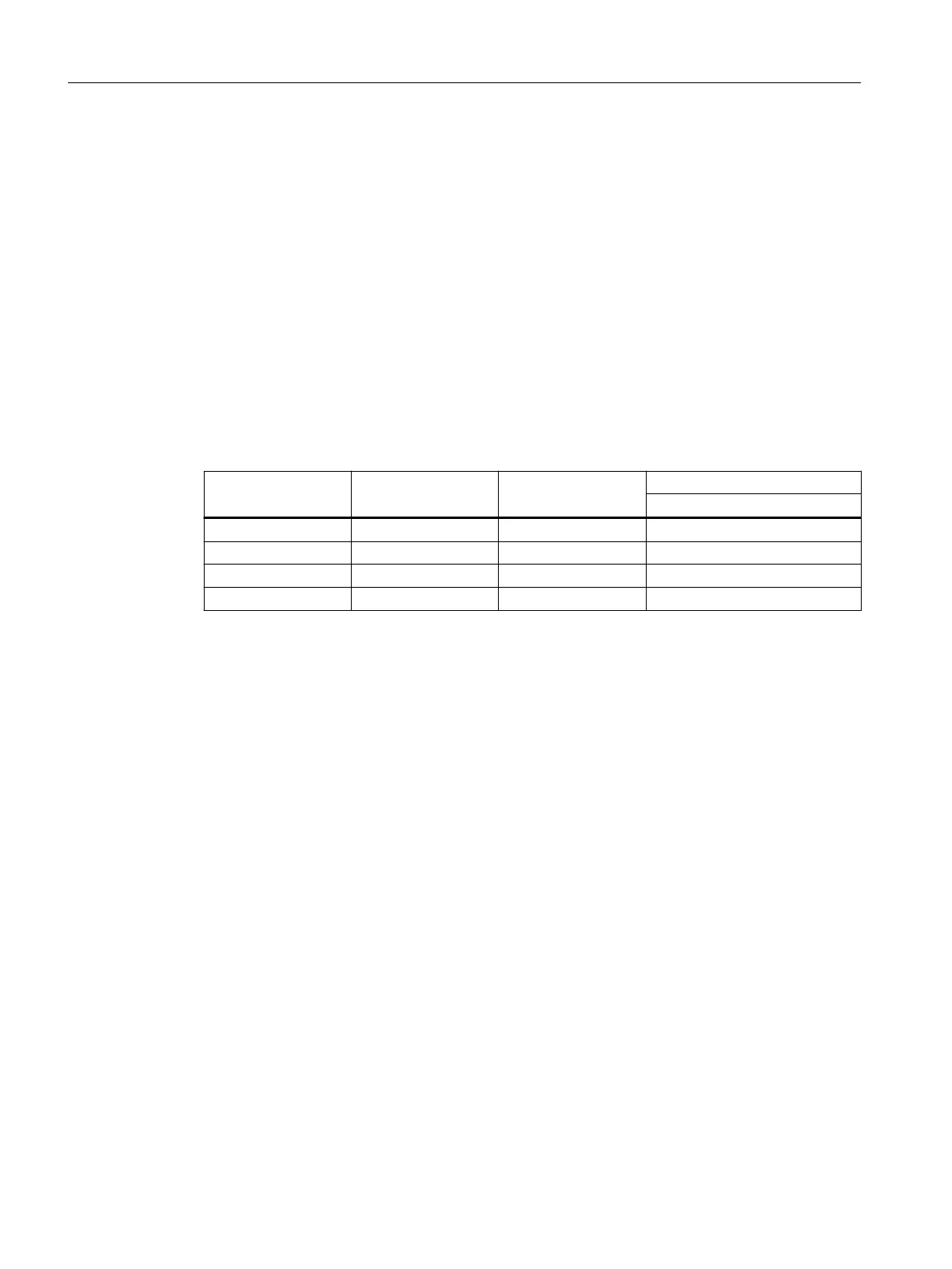
Table 12-35 Tightening torque for the clamping bolt
Gearbox size Thread size Property class Tightening torque
Nm
19, 29 M5 10.9 5
39, 49, 69 M6 10.9 12
79, 89 M8 12.9 35
109 M10 12.9 70
12.3.15.3 Pulling o the shrink disk
Procedure
1. Successively release the clamping bolts⑥ one after the other through a ¼turn each time
using a wrench. Do not completely remove the bolts.
2. Withdraw the shrink disk from the hollow shaft.
Frame sizes79-109:
If the outer ring does not come away from the inner ring, remove some of the clamping bolts
and insert them into neighboring forcing-o threads.
You have withdrawn the shrink disk from the hollow shaft.
12.3.15.4 Cleaning and lubricating shrink disks
Soiled shrink disks must be cleaned and regreased prior to tting.
Shrink disks that have been released need not be disassembled and regreased before being
retensioned.
Additional information on the SIMOGEAR geared motor
12.3Specic data gearbox
SINAMICS G115D Wall Mounted distributed drive
498 Operating Instructions, 07/2023, FW V4.7 SP14, A5E52808211A AA

 Loading...


