Result
The parameters for emulating the saturation characteristic are dened in the converter in
ascending order:
• 20% < p0362 < p0363 < p0364 < p0365
• 20% < p0366 < p0367 < p0368 < p0369
The converter extrapolates the characteristic curve linearly for currents iq > iq[4].
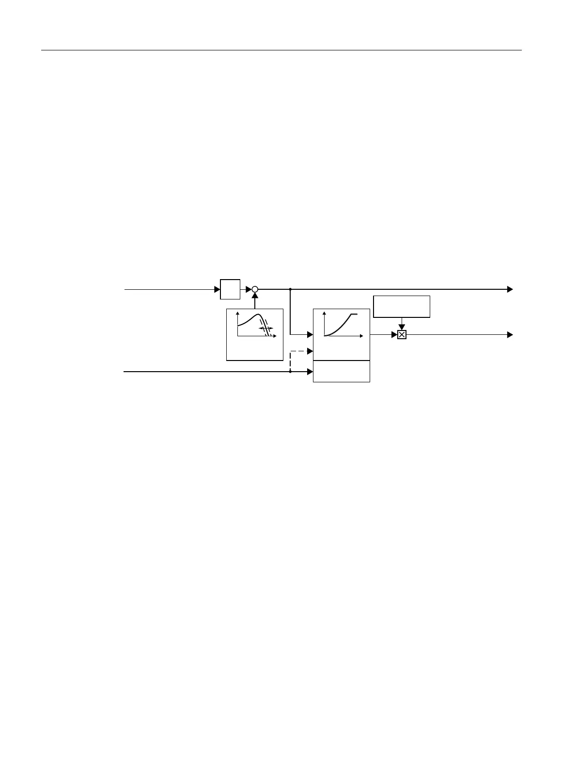
7.20.2 U/f control
Overview
8IFKDUDFWHUL
VWLF
6OLSFRPSHQVD
WLRQ
9ROWDJHERRVW
6RIWVWDUW
QൺI
6SHHGVHWSRLQW
I
VHW
8
VHW
2XWSXWYROWDJH
2XWSXWIUHTXHQF\
&XUUHQWVHWSRLQW,
TBVHW
,
TBVHW
U
U
U
U
0
Q
8
I
1)
In the U/f control variant, "ux current control (FCC)," the converter controls the motor current
(starting current) at low speeds
The U/f control is a speed feedforward control with the following properties:
• The converter sets the output voltage on the basis of the U/f characteristic.
• The output frequency is essentially calculated from the speed setpoint and the number of
pole pairs of the motor.
• The slip compensation corrects the output frequency depending on the load and thus
increases the speed accuracy.
• The omission of a control loop means that the U/f control is stable in all cases.
• In applications with higher speed accuracy requirements, a load-dependent voltage boost
can be selected (ux current control, FCC)
For operation of the motor with U/f control, you must set at least the following subfunctions
appropriate for your application:
• U/f characteristic
• Voltage boost
Advanced commissioning
7.20Motor control
SINAMICS G115D Wall Mounted distributed drive
284 Operating Instructions, 07/2023, FW V4.7 SP14, A5E52808211A AA

 Loading...


