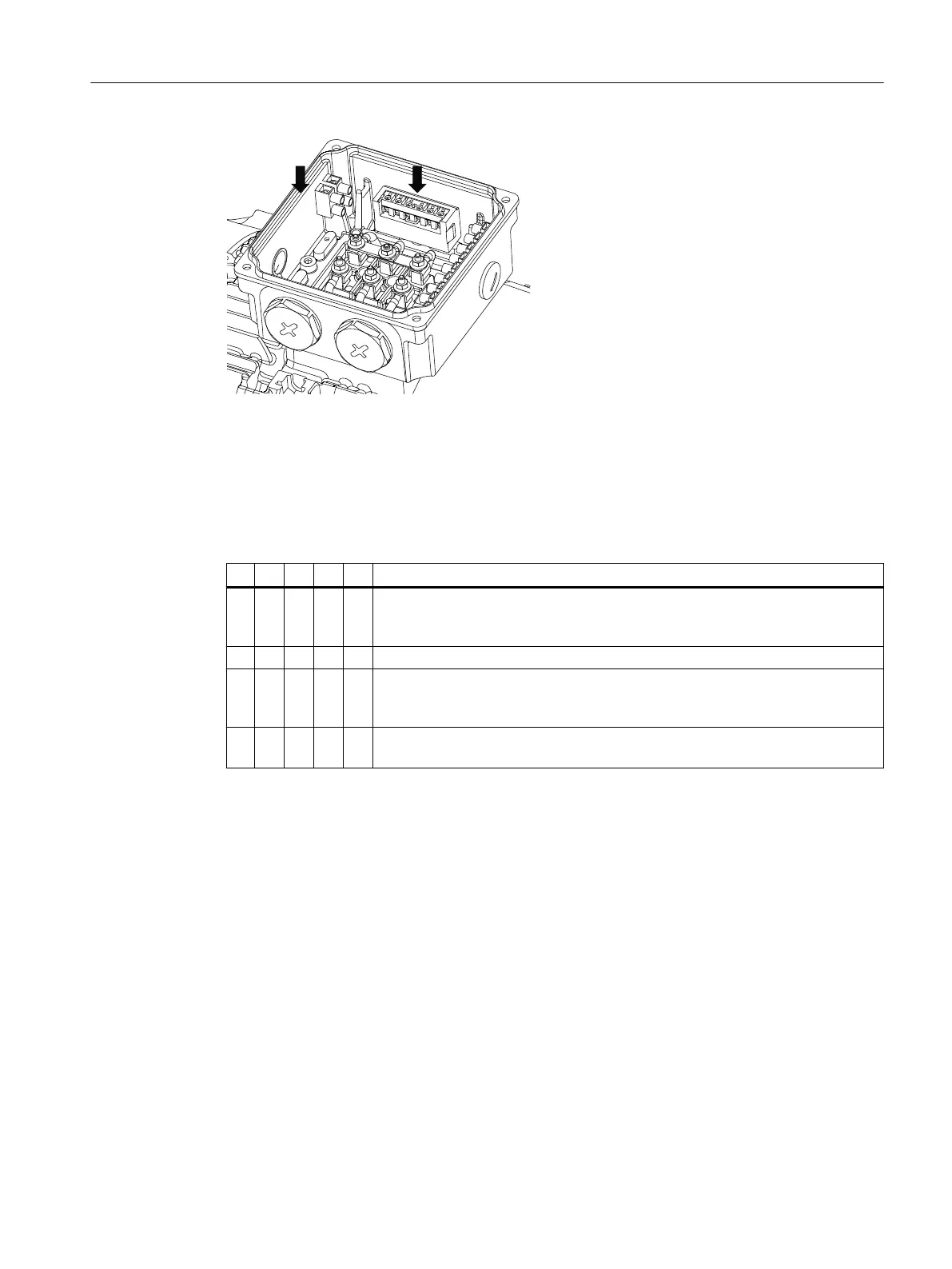
Figure12-7 Fixing in the terminal box
12.2.10.3 Terminal marking
For terminal designations, the following principle denitions apply to three-phase motors:
Table 12-10 Terminal designations using the example 1U1-1
1 U 1 - 1 Designation
x Index showing the pole assignment for pole-changing three-phase motors
(lower number=lower speed)
or, in special cases, for a subdivided winding
x Phase designation (U,V,W)
x Index showing winding start(1)
Index showing winding end(2)
Additional indexes if there is more than one connection per winding
x Additional indices if it is obligatory to connect parallel line feeder cables to sev‐
eral terminals with otherwise identical designations
12.2.10.4 Direction of rotation
The motors are suitable for clockwise and counter-clockwise rotation.
When the line feeder cables are connected in the phase sequenceL1,L2,L3 to U,V,W,
the motor rotates clockwise when looking at the drive end of the shaft extension (DE). If
two of the connections are swapped, the resulting direction of rotation is counter-clockwise,
e.g.L1,L2,L3 to V,U,W.
Additional information on the SIMOGEAR geared motor
12.2Specic data motor
SINAMICS G115D Wall Mounted distributed drive
Operating Instructions, 07/2023, FW V4.7 SP14, A5E52808211A AA 455

 Loading...


