Size Rubber buer Washer
Unten‐
sioned
Tensioned
l1 l1x d6 d1 d5 c6
min
mm mm mm mm mm mm
49 20 18.5 40 12.5 45 6
69 18.5 50
79 17.5
89 30 28 60 21 75 8
Procedure
1. Use the washers according to the table above.
2. Use two nuts to secure the screw connection (lock nuts).
3. Tighten the screwsuntil the rubber buers are pretensioned to the dimensionl1x.
You have now mounted the torque arm.
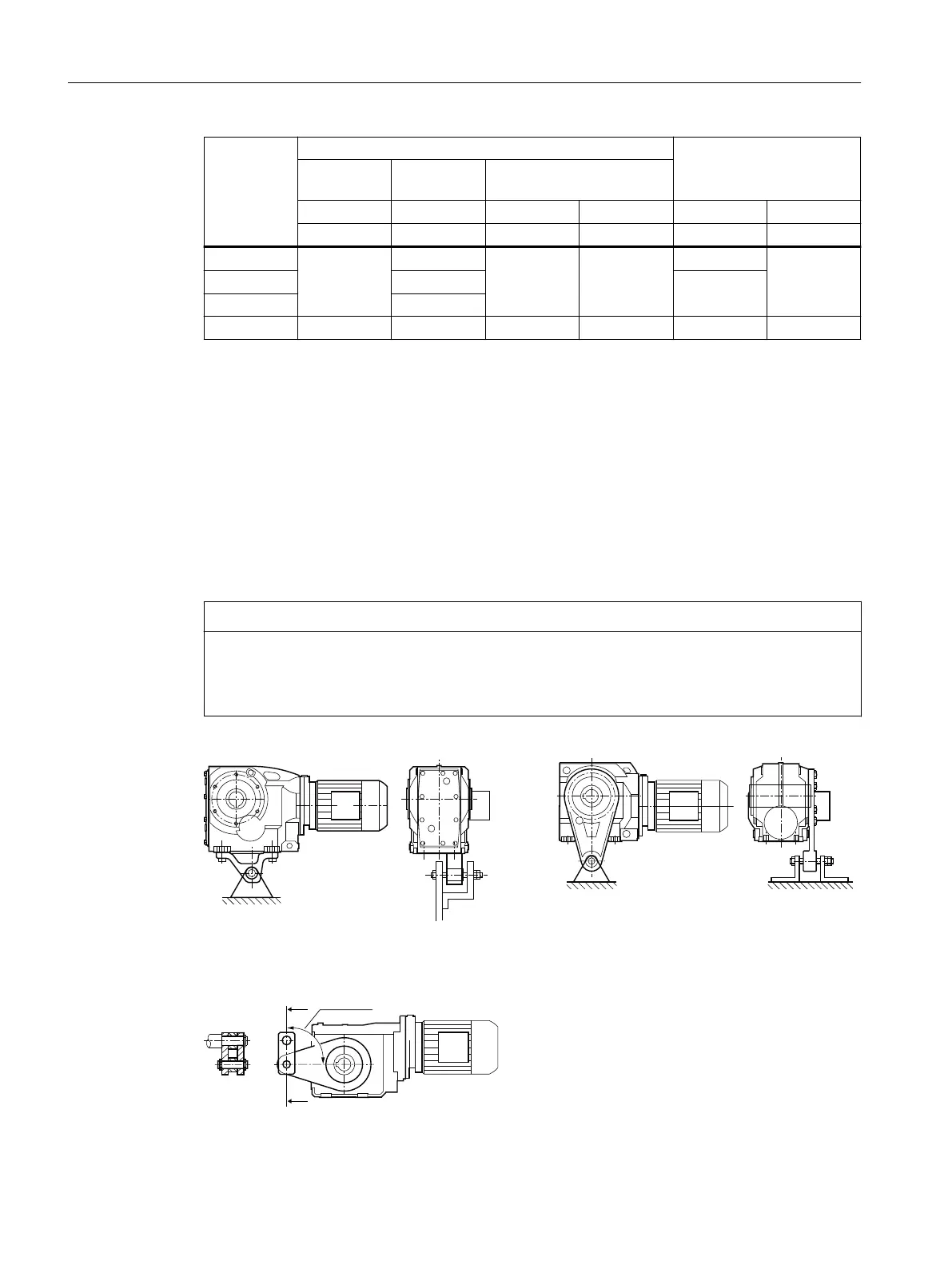
12.3.18.3 Mounting torque arms on bevel gearboxes and helical worm gearboxes
NOTICE
Impermissible loading caused by incorrect mounting
The torque arm bush must be supported by bearings on both sides.
After assembly, the sleeve must have some axial play.
Figure12-27 Mounting suggestion for torque arm on foot and ange
The torque arm can be tted in various positions, depending on the hole circle pitch.
Figure12-28 Toggle lever design
Additional information on the SIMOGEAR geared motor
12.3Specic data gearbox
SINAMICS G115D Wall Mounted distributed drive
506 Operating Instructions, 07/2023, FW V4.7 SP14, A5E52808211A AA

 Loading...


