12.2.10.6 External grounding
Ensure the following when making connections:
• The connecting surface must be bare. Protect the surface against corrosion with a suitable
substance, e.g.acid-free Vaseline.
• Insert the cable lug between the contact bracket and the grounding bracket. Do not remove
the contact bracket which is pressed into the housing.
• Place the spring washer under the screw head.
• Observe the tightening torque for the locking screw, see Mounting and installation (Wall
Mounted) (Page457).
Refer to chapterAUTOHOTSPOT.
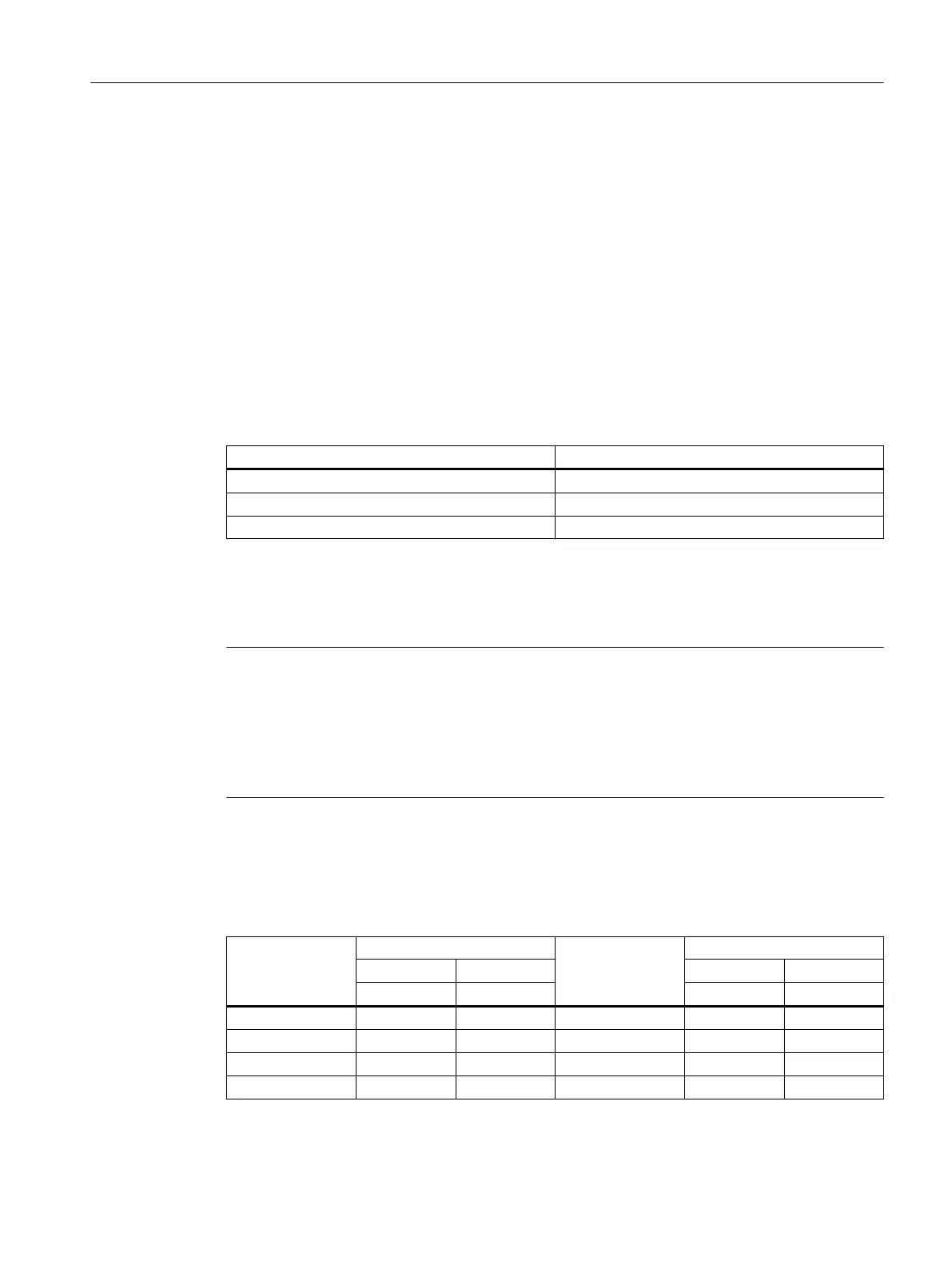
Table 12-12 Maximum conductor connection for external grounding
Motor frame size Thread size
71…90 M4
100…112 M5
132 M6
12.2.10.7 Mounting and installation (Wall Mounted)
See previous sections for the motor-mounted converter.
Note
Match the gland to the connecting cable used:
• Seal insert
• Armor
• Braiding
• Shielding
Screw the gland into the housing. Or secure the gland using a locknut.
Terminal board connection
Table 12-13 Tightening torque for the terminal board connection
Thread size Tightening torque Thread size Tightening torque
Min. Max. Min. Max.
Nm Nm Nm Nm
M4 0.8 1.2 M10 9 13
M5 1.8 2.5 M12 14 20
M6 2.7 4 M16 27 40
M8 5.5 8 ‑ ‑ ‑
Additional information on the SIMOGEAR geared motor
12.2Specic data motor
SINAMICS G115D Wall Mounted distributed drive
Operating Instructions, 07/2023, FW V4.7 SP14, A5E52808211A AA 457

 Loading...


