Glanded variant
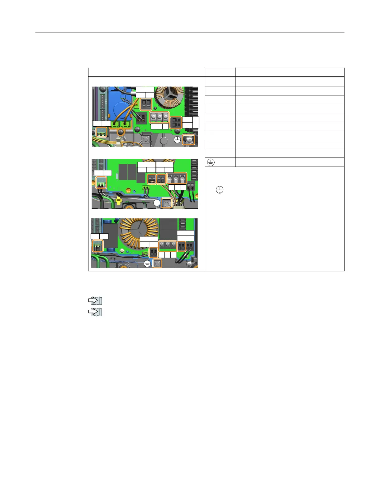
X2 - motor power terminals Signal Description
'4"
'4#
%$
"$
876
5
5
&.
&.
876
55
&.&.
%$
&.&.
"$
&.&.
'4$
"$
876
55
&.&.
%$
&.
&.
U Phase U
V Phase V
W Phase W
EM+ EM brake positive (180VDC)
EM- EM brake negative (180VDC)
EM1 EM brake 1 (400VAC)
EM2 EM brake 2 (400VAC)
T+ Motor temperature sensor positive
T- Motor temperature sensor negative
Protective earth
Screw tightening torque:
• U/V/W: 1.0Nm/8.9lbf.in;
• : 2.2 Nm/19.5 lbf.in
Cable gland size: M25 * 1.5
Further information
Glanded installation kit (Page36)
Cables and connectors (Page64)
5.10.2 Connecting the motor in a star or delta connection
5.10.2.1 Overview
Standard asynchronous motors up to a rated power of approximately 3kW are normally
connected in a star/delta connection (Y/Δ) at 400V/230V. For a 400V line supply, you can
connect the motor to the converter either in a star or in a delta connection.
Wiring
5.10Connecting the motor
SINAMICS G115D Wall Mounted distributed drive
Operating Instructions, 07/2023, FW V4.7 SP14, A5E52808211A AA 75

 Loading...


