❒
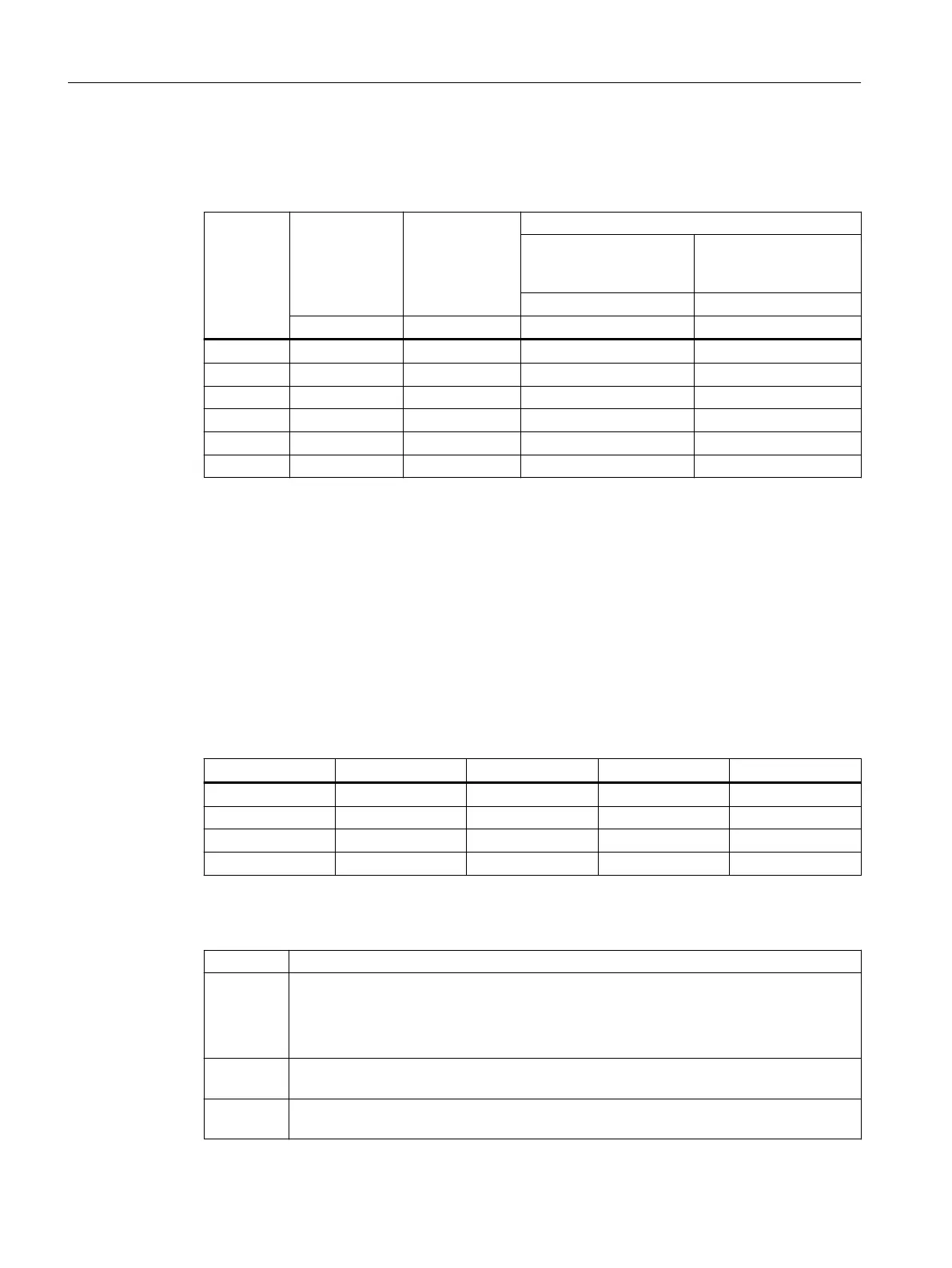
Table 12-24 Brake data
Brake type Nominal air
gap
s
LN
(+0.1/-0.05)
Minimum rotor
thickness
Maximum permissible
Operating speed if max.
permissible operating
energy utilized
No-load speed
with emergency stop
function
Normal friction lining Normal friction lining
mm mm rpm rpm
L4 0.2 4.5 4000 6000
L8 0.2 5.5 4000 5000
L16 0.2 7.5 3600 4000
L32 0.3 8 3600 3600
L60 0.3 7.5 3600 3600
L80 0.3 8 3600 3600
12.2.21 Circuit diagrams
The circuit diagrams include the information about:
• Assembling the connections
• Motor connection
• Use in electric circuit diagrams.
The circuit diagrams are placed in the terminal box, and supplied with the motor.
Table 12-25 Example of the circuit diagram numbering
Example: A 0 100 000
1st position A
2nd position 0
3rd position 100
4th position 000
Table 12-26 Explanation
1st position Identication letter for circuit diagrams.
2nd posi‐
tion
Marking for the connection type:
0: Standard connection at the terminal board (motor), terminal block (auxiliary connec‐
tions).
1: Standard connection at the connector box.
3rd posi‐
tion
Identication for the circuit diagram content.
4th posi‐
tion
Consecutive number for additional versions.
Additional information on the SIMOGEAR geared motor
12.2Specic data motor
SINAMICS G115D Wall Mounted distributed drive
472 Operating Instructions, 07/2023, FW V4.7 SP14, A5E52808211A AA

 Loading...


