Modular structure of the circuit diagrams
The circuit diagrams have a modular structure and have been simplied.
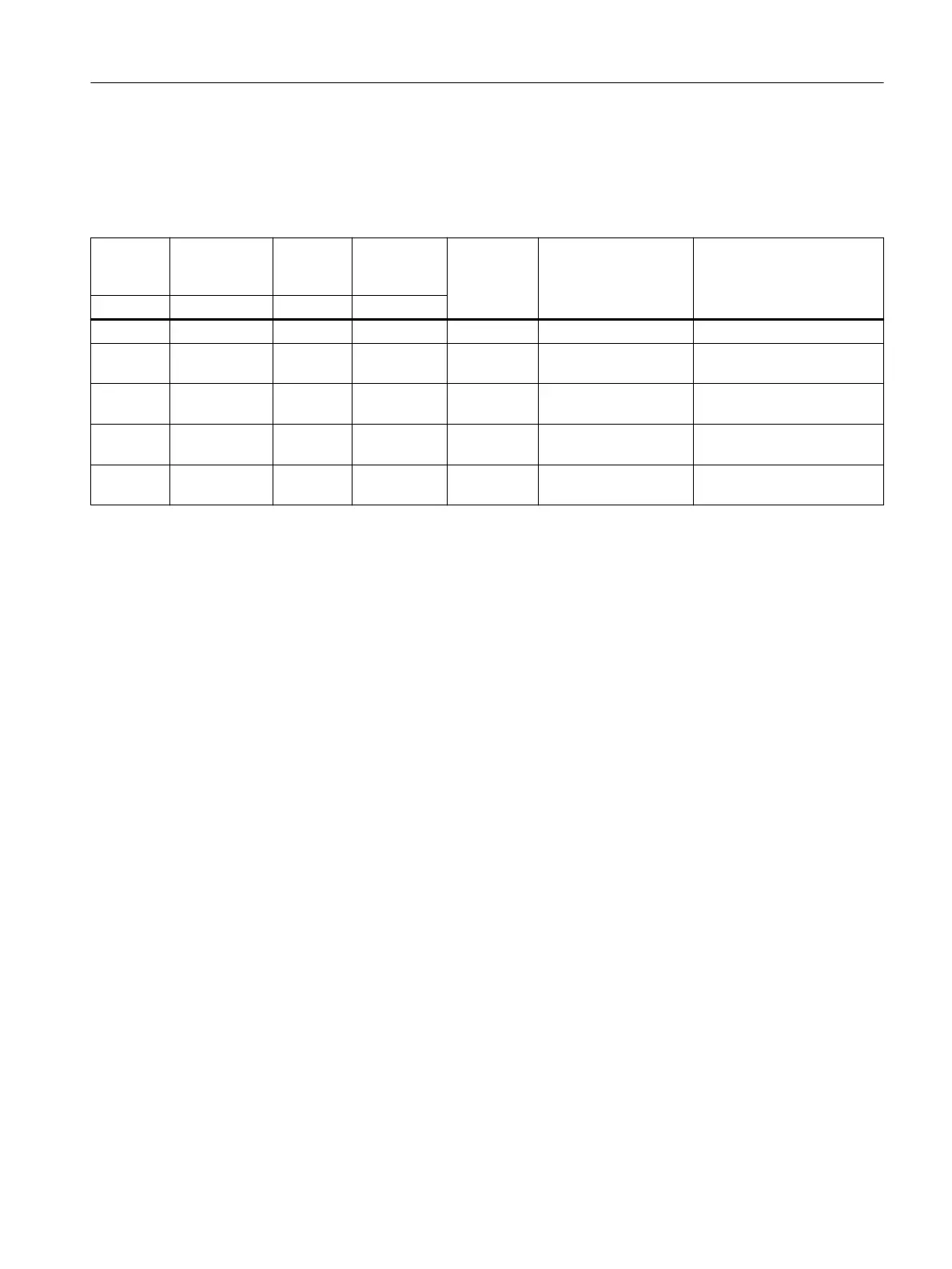
Table 12-27 Structure of the circuit diagrams
Supple‐
mentary
device
Terminal
marking
Supple‐
mentary
device
Terminal
marking
Terminal
numbering
Designation Function
Europe Europe Nema Nema
1BD 1BD1; 1BD2 B B1; B2 05; 06 Brake control DC connection, brake
1BA 1BA1; 1BA2 B B3; B4 07; 08 Brake control AC voltage connection,
brake rectier
1S 1S1; 1S2 B B5; B6 09; 10 Brake control Jumper, DC circuit, brake rec‐
tier
1R 1R1; 1R2 P P27; P28 95; 96 Temperature monitor
motor winding
Resistance thermometer
Pt1000
7R 7R1; 7R2.1;
7R2.2
P P29; P30.1;
P30.2
97; 98.1;
98.2
Temperature monitor
gearbox
Resistance thermometer
1Pt100 oil sensor
Additional information on the SIMOGEAR geared motor
12.2Specic data motor
SINAMICS G115D Wall Mounted distributed drive
Operating Instructions, 07/2023, FW V4.7 SP14, A5E52808211A AA 473

 Loading...


