For a toggle lever design, derive the force in the range of 90°±20°.
Procedure
1. Clean the contact surfaces between the housing and the torque arm.
2. Tighten the bolts to the specied torque.
You have now mounted the torque arm.
Table 12-40 Tightening torque for screws of strength class8.8
Thread size M8 M10 M12 M16 M20 M24 M36
Tightening torque in Nm 25 50 90 210 450 750 2600
12.3.19 General information about commissioning
WARNING
Unintentional starting of the drive unit
Secure the drive unit to prevent it from being started up unintentionally.
Attach a warning notice to the start switch.
WARNING
Risk of slipping on oil
Remove any oil spillage immediately with an oil-binding agent in compliance with
environmental requirements.
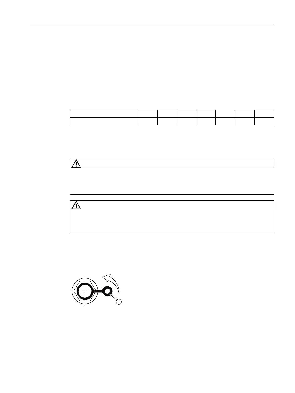
Checking the pressure breather valve
Check that the breather valve is activated.
If the breather valve has a transport xture, it must be removed before commissioning.
Figure12-29 Pressure breather valve with securing clip
Remove the transport xture by pulling the securing clip① in the direction of the arrow.
Additional information on the SIMOGEAR geared motor
12.3Specic data gearbox
SINAMICS G115D Wall Mounted distributed drive
Operating Instructions, 07/2023, FW V4.7 SP14, A5E52808211A AA 507

 Loading...


