Setting the dynamic braking
Param‐
eter
Description Setting
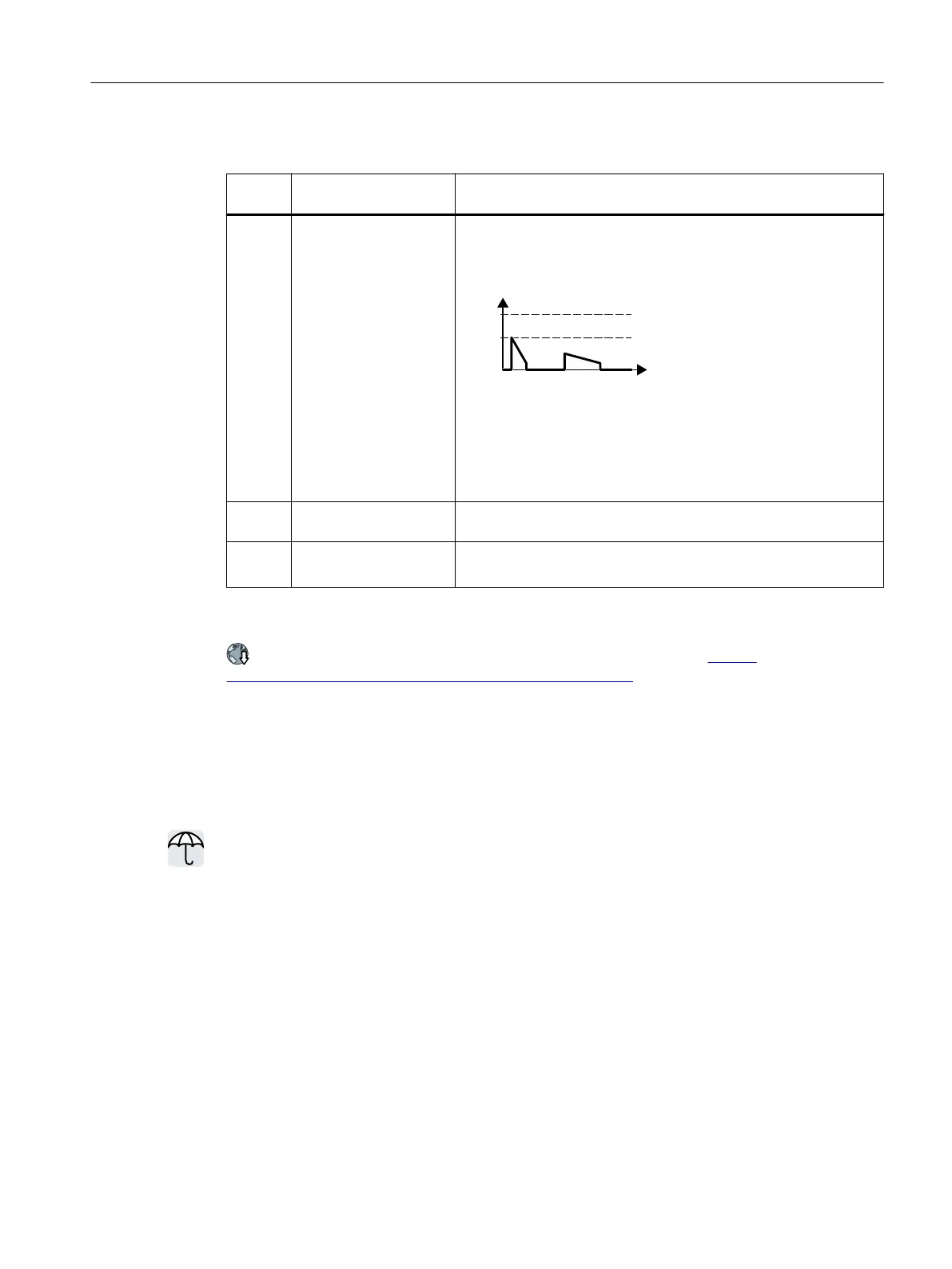
p0219 Braking power of the
braking resistor [kW]
For p0219>0, the converter deactivates the VDC_max controller.
For vector control, p0219 denes the regenerative power limit
p1531.
Using p0219, you dene the maximum braking power that the
braking resistor must absorb.
For an excessively low braking power, the converter extends the
motor ramp-down time.
Factory setting: dependent upon the nominal power of the drive
p0212.
8
Power unit congura‐
tion
If necessary, reduce the activation threshold for the braking resistor.
p0210 Unit supply voltage [V] Sets the drive supply voltage.
Factory setting: 400
An application example for conguring a drive with braking resistor is provided in the
Internet:
Engineering and commissioning series lifting equipment/cranes (https://
support.industry.siemens.com/cs/ww/en/view/103156155)
7.22 Overcurrent protection
Overview
The U/f control prevents too high a motor current by inuencing the output frequency and
the motor voltage (I_max controller).
Requirement
You have selected U/f control.
The application must allow the motor torque to decrease at a lower speed.
Function description
The I_max controller inuences the output frequency and the motor voltage.
If the motor current reaches the current limit during acceleration, the I_max controller
extends the acceleration operation.
Advanced commissioning
7.22Overcurrent protection
SINAMICS G115D Wall Mounted distributed drive
Operating Instructions, 07/2023, FW V4.7 SP14, A5E52808211A AA 315

 Loading...


