A.1.2 Application example
Shift the control logic into the converter
It is only permissible that a conveyor system starts when two signals are present simultaneously.
These could be the following signals, for example:
• The oil pump is running (the required pressure level is not reached, however, until after 5
seconds).
• The protective door is closed.
To implement this task, you must insert free function blocks between digital input 0 and the
command to switch on the motor (ON/OFF1).
212))
S S
S>@
U
S >PV@
S
S
7
3'(
S>@
U
U
U
S>@
$1'
',
',
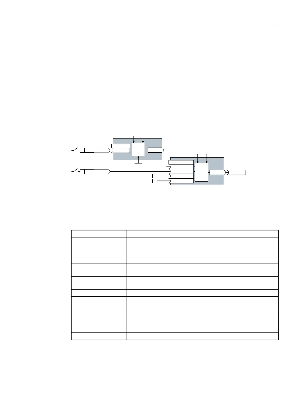
The signal of digital input0 (DI0) is fed through a time block (PDE0) and is interconnected
with the input of a logic block (AND 0). The signal of digital input 1 (DI 1) is interconnected to
the second input of the logic block. The logic block output issues the ON/OFF1 command to
switch on the motor.
Setting the control logic
Parameter Description
p20161 = 5 The time block is enabled by assigning to runtime group5 (time slice of
128ms)
p20162 = 430 Run sequence of the time block within runtime group 5 (processing before
the AND logic block)
p20032 = 5 The AND logic block is enabled by assigning to runtime group 5 (time slice of
128ms)
p20033 = 440 Run sequence of the AND logic block within runtime group5 (processing
after the time block)
p20159 = 5000.00 Setting the delay time [ms] of the time module: 5 seconds
p20158 = 722.0 Connect the status of DI 0 to the input of the time block
r0722.0 = Parameter that displays the status of digital input 0.
p20030[0] = 20160 Interconnecting the time block to the 1st AND input
p20030[1] = 722.1 Interconnecting the status of DI 1 to the 2nd AND input
r0722.1 = Parameter that displays the status of digital input 1.
p0840 = 20031 Interconnect the AND output to ON/OFF1
Appendix
A.1Interconnecting signals in the converter
SINAMICS G115D Wall Mounted distributed drive
Operating Instructions, 07/2023, FW V4.7 SP14, A5E52808211A AA 583

 Loading...


