Procedure
1. Remove the fan cover.
2. Loosen the xing screws of the brake.
3. Screw the sleeve screws further into the solenoid using an open-ended spanner.
4. Tighten the xing screws of the brake.
5. Check the air gaps
LN
in the vicinity of the screws using a feeler gauge.
6. If necessary, correct the air gaps
LN
and then check it again.
7. When combined with manual brake release:
Check the setting dimensions
HL
and corrects
HL
if necessary.
8. Mount the fan cover.
You have now set the air gap.
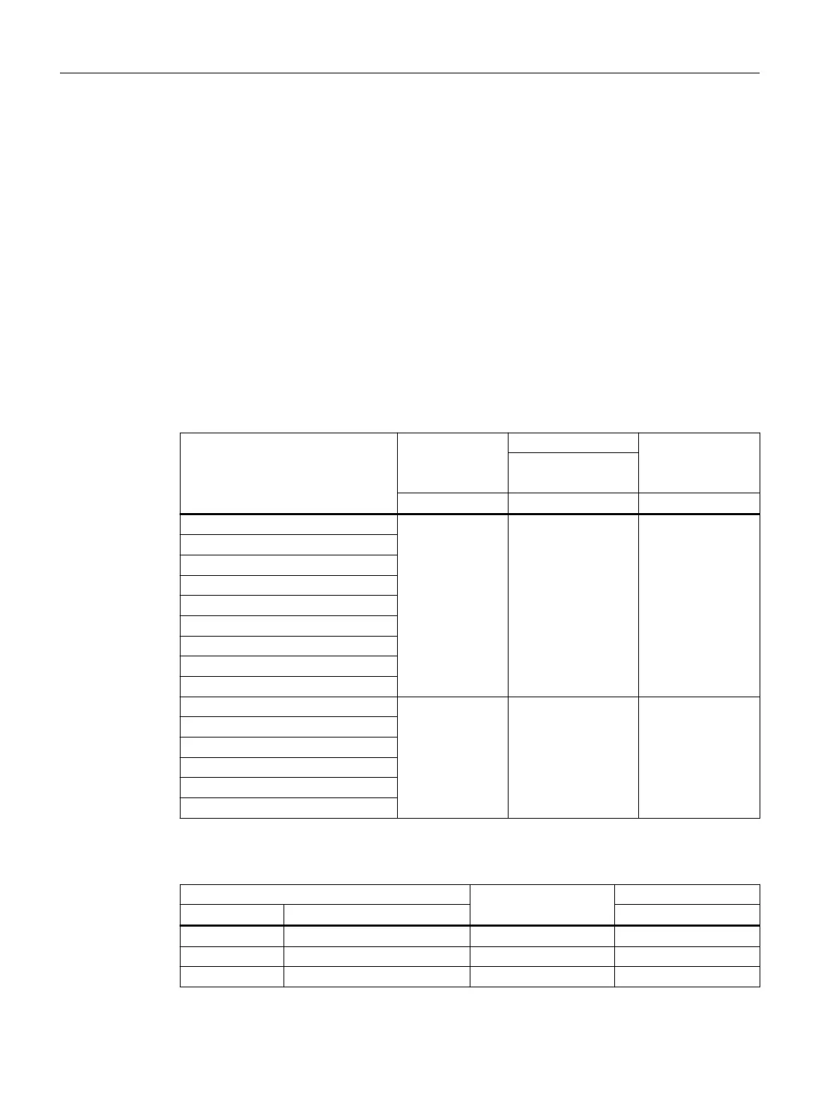
Table 12-22 Air gap values
Brake type Nominal air gap
s
LN
(+0.1/-0.05)
Maximum air gap for Reference gage
s
HL
Standard excitation
s
Lmax.
mm mm mm
L4/1,4 0.2 0.3
1.0
L4/2
L4/3
L4
L8/4
L8/5
L8
L16/8, L16/10, L16/13, L16
L16/20
L32/14, L32/18 0.3 0.45 1.5
L32/23
L32, L60/50
L32/40
L80/25, L80/35, L80/50, L80/63
L80/100
Table 12-23 Tightening torque for the brake screw
Brake type Thread size Tightening torque
Siemens Brake supplier Nm
L4 INTORQBABFK458(06E) 3xM4 3
L8 INTORQBABFK458(08E) 3xM5 6
L16 INTORQBABFK458(10E) 3xM6 10
Additional information on the SIMOGEAR geared motor
12.2Specic data motor
SINAMICS G115D Wall Mounted distributed drive
470 Operating Instructions, 07/2023, FW V4.7 SP14, A5E52808211A AA

 Loading...


