Technical data of external braking resistor
The external braking resistors are not included in the scope of delivery of the G115D converter.
The following optional external braking resistors are available.
G115D wall-
mounted con‐
verter
External braking resistor
Fra
me
Siz
e
Rated pow‐
er
Resist‐
ance
(+/-10%)
Continu‐
ous brak‐
ing power
Peak brak‐
ing
power
1)
Article number Vibra‐
tion and
shock
during
opera‐
tion
Sur‐
round‐
ing tem‐
perature
FSA 0.37 kW to 1
.5kW
210Ω 200W 1200W 6SL3501-1BE32-0AA
0
Class
3M2, test
accord‐
ing to EN
60721-3-
3
-30 °C to
+55 °C
220Ω 240W 1440W 6SL3501-1BE32-4AA
0
200Ω 480W 2880W 6SL3501-1BE34-8AA
0
FSB 2.2kWto4
kW
160Ω 200W 1200W 6SL3501-1BE32-0BA
0
150Ω 240W 1440W 6SL3501-1BE32-4BA
0
150Ω 600W 3600W 6SL3501-1BE36-0BA
0
FSC 5.5kWto7.
5kW
81Ω 600W 3600W 6SL3501-1BE36-0CA
0
72Ω 1200W 7200W 6SL3501-1BE41-2CA
0
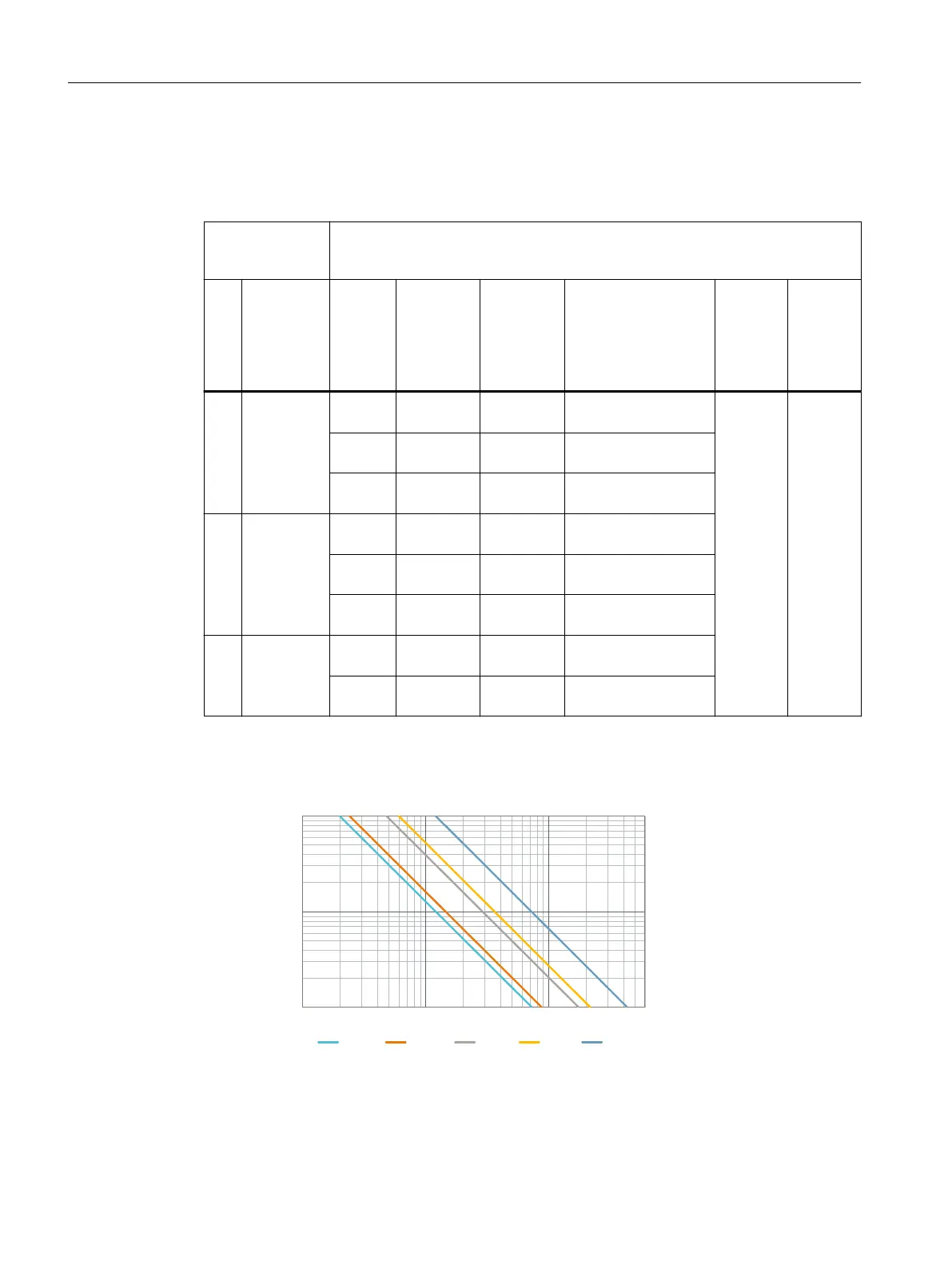
1)
Peak braking power at 10% cycle time of a 120s cycle. For the peak braking power at dierent duty
cycles, refer to the following diagram.
%VUZDZDMF<>
#SBLJOHQPXFS
"UBNCJFOUUFNQFSBUVSFPG
<8>
88888
Technical data
11.1Technical data of the G115D wall-mounted converter
SINAMICS G115D Wall Mounted distributed drive
416 Operating Instructions, 07/2023, FW V4.7 SP14, A5E52808211A AA

 Loading...


