Use a tting device to t the input or output elements.
Figure12-16 Example of a tting device
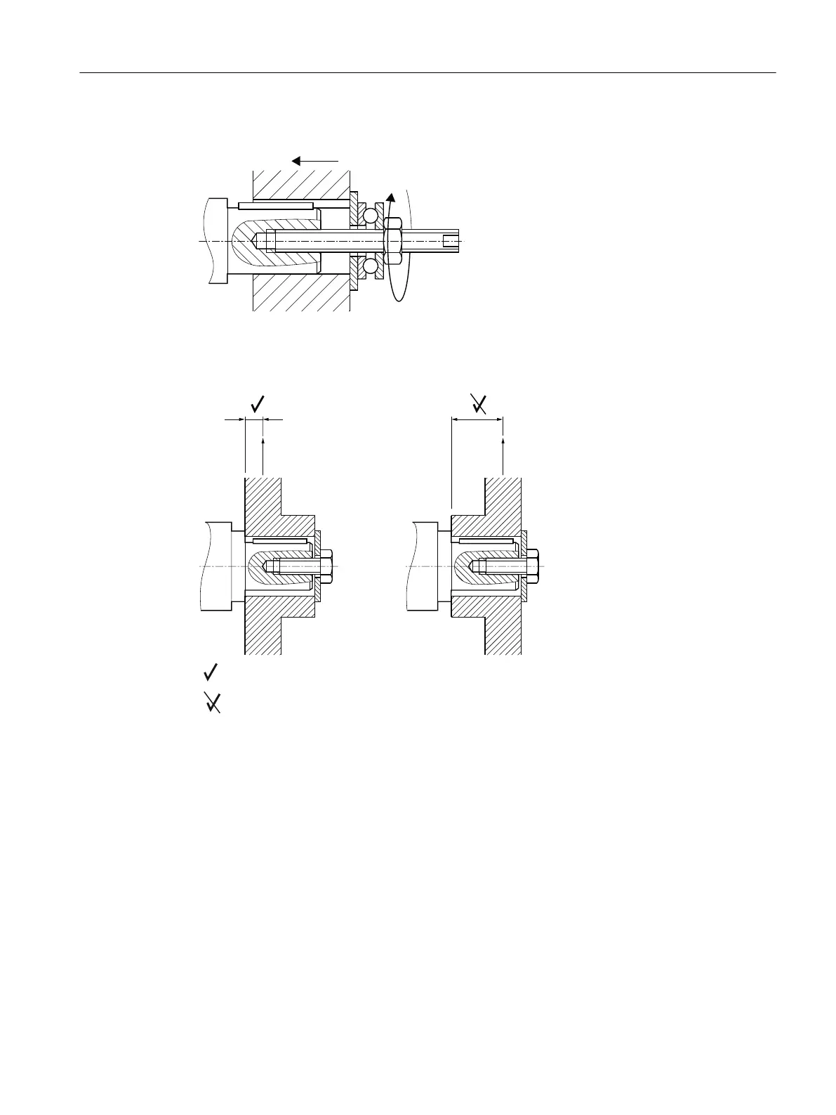
Observe the correct mounting arrangement to minimize stress on shafts and bearings due to
lateral forces.
Correct
Incorrect
a Hub
F Force
Figure12-17 Mounting arrangement for low stress on shafts and bearings
Procedure
1. Use benzine or a solvent to remove the anti-corrosion protection from the shaft ends and
anges. Or remove the existing protective skin.
2. Fit the drive input and output elements to the shafts. Lock the elements.
You have now attached the input or output element.
Additional information on the SIMOGEAR geared motor
12.3Specic data gearbox
SINAMICS G115D Wall Mounted distributed drive
Operating Instructions, 07/2023, FW V4.7 SP14, A5E52808211A AA 489

 Loading...


