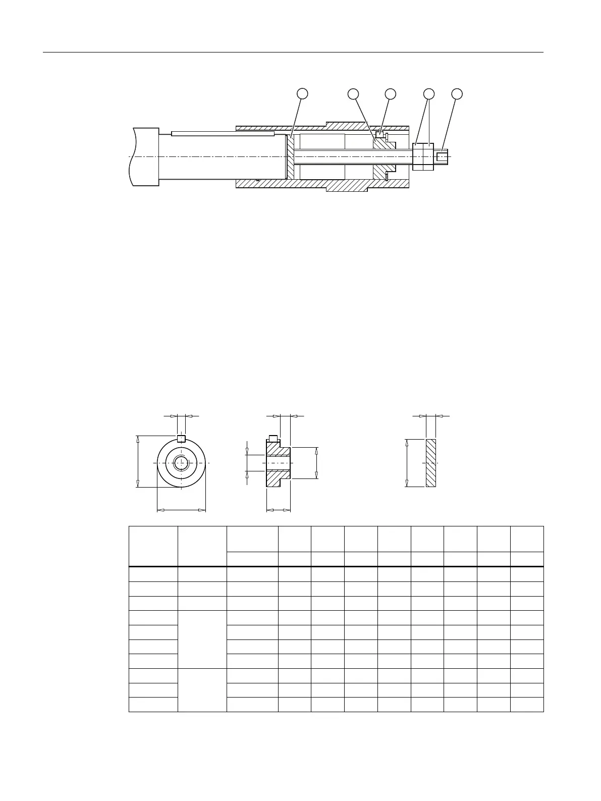
Items①to⑤ are not included in the scope of supply.
① Disk ④ Hexagon nut
② Threaded block ⑤ Threaded spindle
③ Parallel key
Figure12-21 Removing the hollow shaft with parallel key
Procedure
1. Remove the axial locking element from the hollow shaft.
2. Drive out the machine shaft using the disk ①, threaded block ②, parallel key ③, threaded
spindle⑤ and hexagon nuts④.
You have now removed the hollow shaft with parallel key.
Design suggestion for threaded block and disk
G
V
G
E
G
E
E
X
W
Gearbox Size Hollow
shaft ∅
b10 b11 b12 d10 d11 s11 t
max
u
mm mm mm mm mm mm mm mm mm
B 19 20 3 15 10 19.9 10 M6 22.5 6
B, C 29 20 3 15 10 19.9 10 M6 22.5 6
B, F 29 25 3 15 10 24.9 16 M10 28 8
C 39 25 3 15 10 24.9 16 M10 28 8
B, K, F, C 30 6 15 10 29.9 18 M10 33 8
B 35 6 15 10 34.9 24 M12 38 10
B 40 6 15 10 39.9 28 M16 43 12
C 49 30 6 15 10 29.9 18 M10 33 8
K, F, C 35 6 15 10 34.9 24 M12 38 10
B 40 6 15 10 39.9 28 M16 43 12
Additional information on the SIMOGEAR geared motor
12.3Specic data gearbox
SINAMICS G115D Wall Mounted distributed drive
494 Operating Instructions, 07/2023, FW V4.7 SP14, A5E52808211A AA

 Loading...


