Procedure
1. Attach the torque arm⑦ to the gearbox, as shown in Torque arms with slip-on gearboxes
(Page505).
2. Remove the corrosion protection coating using white spirit or a solvent on:
– The shaft ends of the machine shaft①
– The clamping ring③
– The bronze bushing②.
3. Check the seats or edges of the hollow shaft⑥ and the machine shaft① for damage.
Contact Technical Support if you notice any damage.
4. Place the clamping ring③ on the bronze bushing②.
5. Position the bronze bushing ② with the clamping ring ③ on the machine shaft ①. Observe
the tightening torque of the tightening bolt④ and the tolerance dimensionto10.
6. Oil lightly the locating holes in the hollow shaft⑥ for the tapered bushing⑨ and bronze
bushing②. Remove any excessive oil using a clean cloth.
7. Push the gearbox with the installed torque arm⑦ on the machine shaft① against the
clamping ring③.
8. Tighten the torque arm⑦ with the bolts⑧ only gently because the gearbox must have
clearance for the subsequent mounting.
9. Ensure that the thrust collar ⑤ is placed at the correct position.
If the thrust collar ⑤ is not placed at the correct position, bring the ring ⑤ into the correct
position by tightening the tightening bolts⑩ with turned tapered bushing ⑨.
10.Place the tapered bushing⑨ on the machine shaft①.
11.Use the torque wrench to turn each of the tightening bolts⑩ equally (not crosswise),
repeating this procedure several times. Observe the tightening torque of the tightening
bolt⑩.
12.Tighten the bolts⑧ of the torque-arm fastening, as shown in Torque arms with slip-on
gearboxes (Page505).
13.Attach the rubber cover or protection cover⑪ included in the scope of delivery, as shown
in Removing and installing the protection cover (Page490).
You have installed the SIMOLOC assembly system.
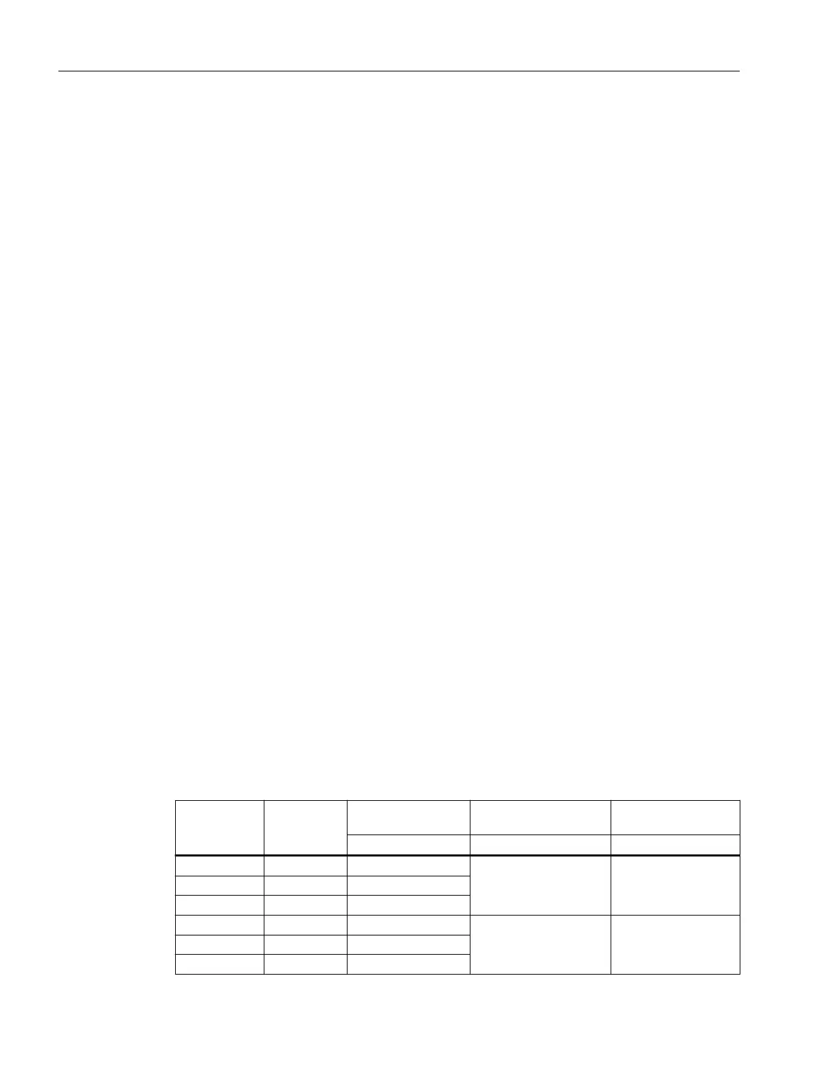
Table 12-37 Tolerance dimension, tightening bolt④ tightening torque
Gearbox type Size Tolerance dimen‐
sion to10
Thread size④ Tightening torque
mm Strength class10.9 Nm
F, B, C 29 0.6...2.1 M6 15
F, B, K, C 39 0.7...2.2
F, B, K, C 49 0.8...2.6
F, K, C 69 0.7...2.5 M8 35
F, K 79 1.4...3.2
F, K, C 89 1.5...3.4
Additional information on the SIMOGEAR geared motor
12.3Specic data gearbox
SINAMICS G115D Wall Mounted distributed drive
502 Operating Instructions, 07/2023, FW V4.7 SP14, A5E52808211A AA

 Loading...


