Grounding and high-frequency equipotential bonding measures
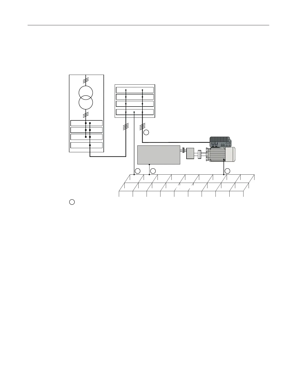
The following gure illustrates all grounding and high-frequency equipotential bonding
measures using an example of the SINAMICS G115D Motor Mounted drive.
7UDQVIRUPHU
)RXQGDWLRQ
'ULYHQPDFKLQH
6HFRQGOHYHOGLVWULEXWLRQ
ZLWKHTXLSRWHQWLDO
ERXQGLQJ3(
&RQYHQWLRQDOJURXQGLQJV\VWHPZLWKRXWVSHFLDOKLJKIUHTXHQF\SURSHUWLHV
3(
/
/
/
3(
/
/
/
The ground connections ① represent the conventional grounding system for the drive
components. They are made with standard, heavy-power PE conductors without special high-
frequency properties and ensure low frequency equipotential bonding as well as protection
against injury.
The line supply cable of the converter can be unshielded. The converter has to be grounded
by this cable.
The converter enclosure provides high-frequency equipotential bonding between the
converter and the motor.
The connection provides solid bonding for high-frequency currents between the metal body
of the converter and the unpainted metal mounting frame. This connection should be made
with short, nely stranded, braided copper wires.
Additional measures
Finely stranded, braided copper cables have to be routed in parallel with the cable shields in the
following cases:
• Old installations with already existing unscreened cables
• Cables with poor high-frequency properties
• Installations with bad grounding systems
Wiring
5.1EMC installation guidelines
SINAMICS G115D Wall Mounted distributed drive
Operating Instructions, 07/2023, FW V4.7 SP14, A5E52808211A AA 51

 Loading...


