SV-EMS-220/221 Installation and Configuration
7-2 SkyView System Installation Guide - Revision AA
specified) SkyView display (typically, the Left Engine is displayed on the left display and the
Right Engine is displayed on the right display). Note: Only SkyView Classic provides support for
dual SV-EMS-220/221 modules. SkyView SE and SkyView HDX (as of Software v15.0) do not
support this feature.
Note that Dynon Avionics provides preconfigured sensor mapping and settings files as well as
premade engine sensor connection wire harnesses. These resources support many popular four
and six-cylinder engine installations. Reference the Example Engine Sensor and Transducer
Installations Section for examples.
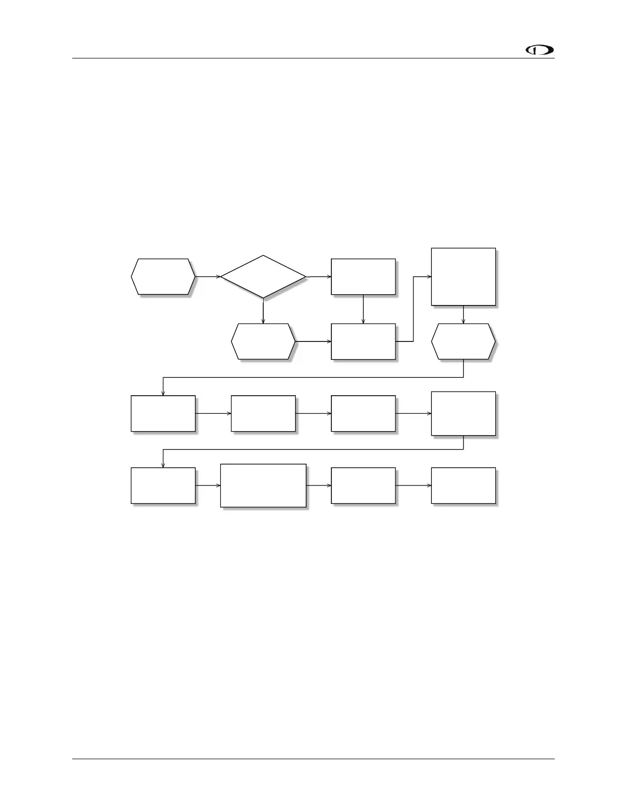
Figure 56 is a high-level overview of a suggested installation, configuration, and calibration
procedure for the SV-EMS-220/221 and its associated wiring, sensors, and transducers.
Figure 56 – Suggested SV-EMS-220/221 Installation and Configuration Procedure