SV-EMS-220/221 Installation and Configuration
7-56 SkyView System Installation Guide - Revision AA
For Dynon Avionics P/N 100411-000 and P/N 100411-001 pressure sensors, if
Teflon tape or other sealant is used, ensure the sensor casing still maintains a
good connection to ground.
Rotax 914 Differential Fuel Pressure Sensor
The fuel pressure sensors that Dynon Avionics sells are not suitable for use with
the Rotax 914 engine, as Rotax specifies that fuel pressure on the 914 engine be
measured with respect to the air box pressure. All fuel pressure sensors sold by
Dynon Avionics are only capable of measuring fuel pressure against ambient air
pressure.
The UMA N1EU07D sensor is a differential pressure sensor which measures fuel pressure with
respect to air box pressure as required by the 914 engine. One UMA N1EU07D sensor is
installed on 914 engines, but that sensor is dedicated to the 914 ECU, and the output of the
sensor cannot be shared between the ECU and SkyView. To display a 914 engine’s fuel pressure
on SkyView, a second UMA N1EU07D sensor must be purchased and installed. This sensor is not
supplied by Dynon Avionics.
Install the differential fuel pressure sensor in an area convenient to the connections on the
engine. The mounting threads are 5/8-18. Connect side of sensor marked with a “W” to the fuel
line close to the carburetors. Use 1/8-27 pipe thread fitting. Connect the other side of sensor to
the air box. This can be done by inserting a “T” in the carb vent lines that go to the air box. Use
a 1/8-27 pipe thread, barbed insert into the sensor. Make sure all fittings on the air box lines
are tight using spring clamps or tie wraps.
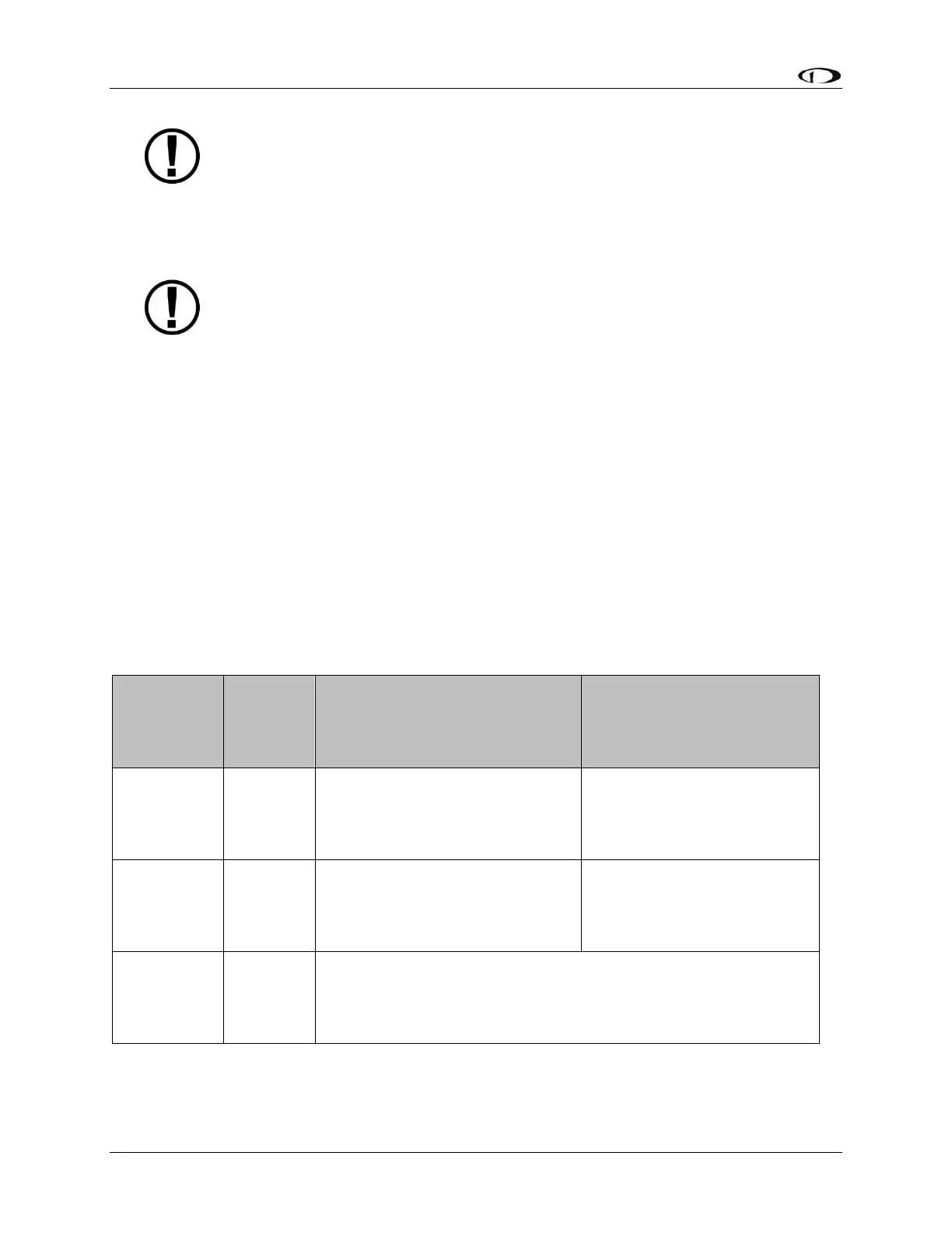
UMA
N1EU07D
Sensor
Wire Color
SV-EMS-220/221
Wire Color
SV-EMS-220/221
Pin Number
Red
It is acceptable to share this pin
/ wire with other sensors; see
Table 32 above.
15
It is acceptable to share this
pin / wire with other
sensors; see Table 32 above.
Any of Pin 3, 13, 16, 17, or
30. It is acceptable to share
this Ground with other
sensors.
Any of Pin 8 (Brown), or
Pin 22 (Violet/Yellow), or
Pin 23 (Violet/Green), or
Pin 31 (White/Orange)
Table 57 – UMA N1EU07D Wiring