SV-EMS-220/221 Installation and Configuration
7-62 SkyView System Installation Guide - Revision AA
If you have a VP-X system (SkyView Classic only) in your
avionics system, use either position A or position B.
Position C is not useful in a VP-X installation because the
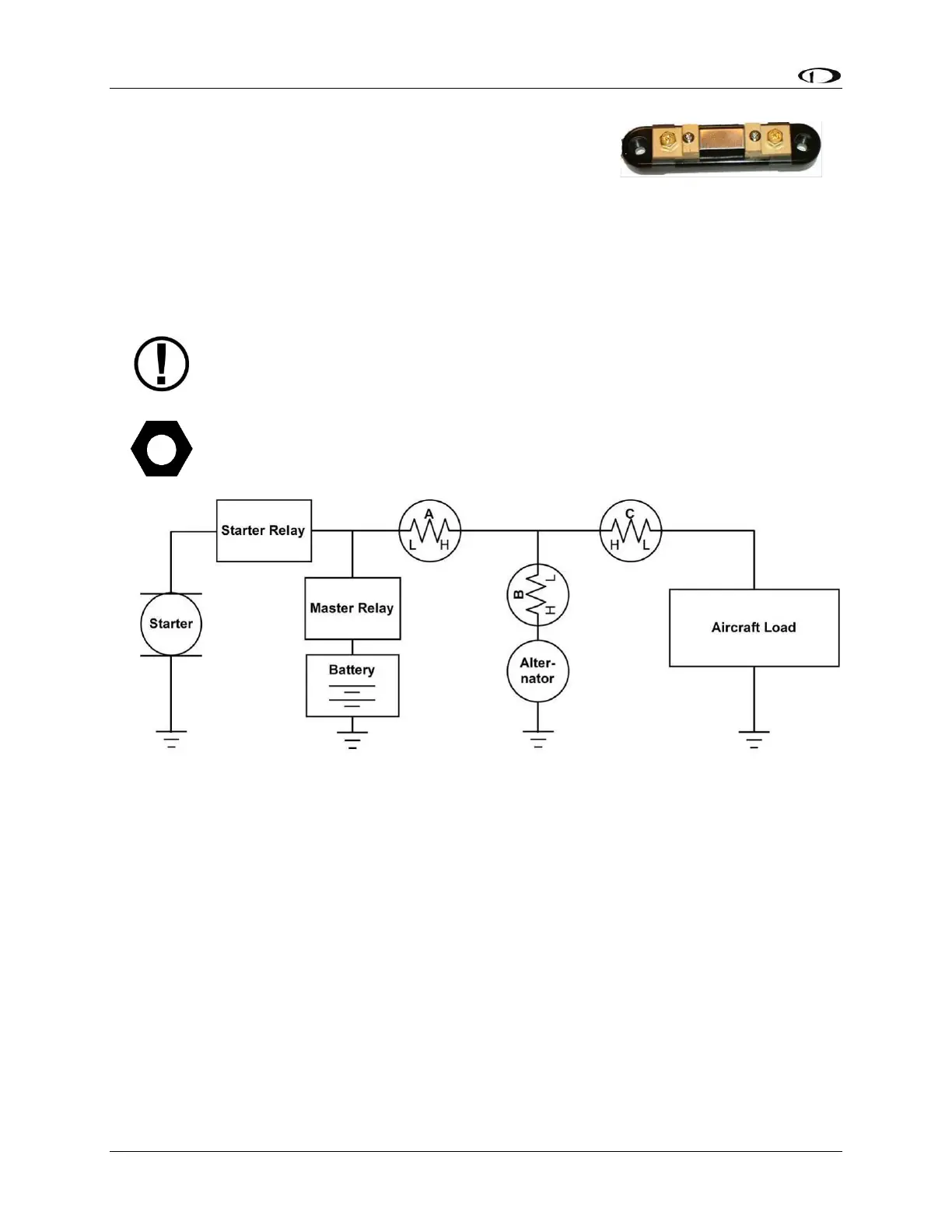
VP-X measures aircraft loads directly. Position A – Ammeter
indicates current flow into or out of your battery. In this
position, it will show both positive and negative currents (i.e., -60 amps to +60 amps).
Position B–Ammeter indicates only the positive currents flowing from the alternator to
both the battery and aircraft loads. (0A-60A)
Position C–Ammeter indicates the current flowing only into the aircraft loads. (0A-60A)
Note that the ammeter shunt is not designed for the high current required by the
starter and must not be installed in the electrical path between the battery and
starter.
The Ammeter Shunt packaging may be marked 40mV/40A. However, Dynon
Avionics rates the shunt for up to 60A loads.
Figure 75 – Recommended Amps Shunt Locations (simplified electrical diagram)
Use two ¼” ring terminals sized appropriately for the high-current wire gauge you will be
routing to and from the ammeter shunt. Cut the wire where you would like to install the
ammeter shunt. Strip the wire and crimp on the ring terminals. Using a Phillips screwdriver,
remove the two large screws (one on either end of the shunt), slip the ring terminals on, and
screw them back into the base.
We highly recommend that you fuse both the connections between the shunt and the SV-EMS-
220/221 as shown in Figure 76 below. There are two methods for accomplishing this. You may
simply connect two 1 amp fuses in-line between the shunt and the SV-EMS-220. Or, you may
use butt splices to connect 1” to 2” (25mm to 50mm) sections of 26 AWG wire between the
shunt and each of the Amps leads connecting to the SV-EMS-220. These fusible links are a
simple and cost-effective way to protect against short-circuits (fusible links in LSA installations
may not be ASTM-compliant).