SV-EMS-220/221 Installation and Configuration
SkyView System Installation Guide - Revision AA 7-63
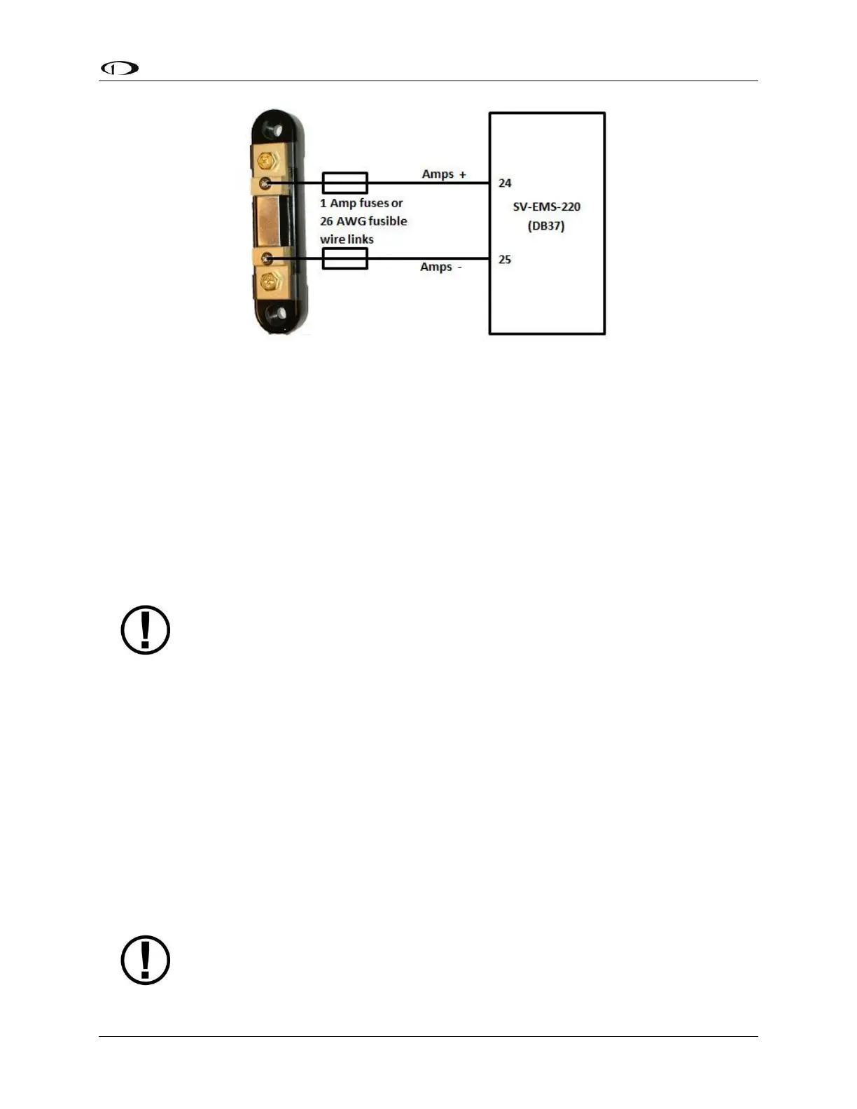
Figure 76 – Amps Shunt Fuse / Wire Connection Diagram
Next, crimp the two supplied #8 ring terminals onto the wires using the fusing method chosen
above. Connect the other ends of the fuses to the Amps High and Amps Low leads (pins 24 and
25) on the EMS 37-pin Main Sensor Harness. Unscrew the two smaller screws on the ammeter
shunt. Slide the ring terminals onto them and screw them back into the base. Connect the
“Amps High” lead to the side of the shunt marked by “H” in Figure 75; connect the “Amps Low”
lead to the side marked by “L”.
If you find that the current reading displayed on the EMS page is the opposite polarity of what
you want, swap the two signal inputs (Amps High and Amps Low) to obtain the desired result.
It is extremely important that you secure all loose wires and ensure that exposed
terminals cannot touch or short out to other objects in the plane. All metal on the
shunt is at the same voltage as–and carries the same risks as–the positive terminal
on the battery. Improperly installing the ammeter shunt can result in high current
flow, electrical system failure, or fire.
GRT CS-01 and CS-02 Hall Effect Current Sensor
These sensors are available from GRT Avionics, and can be used as alternatives to the AMPS
SHUNT sensor supplied by Dynon Avionics in its EMS kits for measuring DC current flow in your
electrical system. Support for the CS-02 was added in SkyView Software v13.0 with SkyView
EMS Sensor Definition File Revision 46371 dated 2015-07-16 (and later).
Reference the documentation included with the CS-01 or CS-02 for additional connection
details.
The GRT CS-01 can monitor DC current up to +/- 100 Amps.
The GRT CS-02 can measure DC current up to +/- 50 Amps.
If you purchase a Dynon Avionics EMS sensor / harness kit, the AMPS SHUNT will
be included in the kit; it cannot be returned for refund.