SV-XPNDR-261/262 Installation and Configuration
11-6 SkyView System Installation Guide - Revision AA
The SV-XPNDR-261/262 package includes a 25-pin connector and pins if you wish to fabricate
your own harness. Refer to the sections below for detailed wiring information. Note that your
connector kit may contain a 1.21K resistor. This resistor is only used if you intend to connect a
certified GPS receiver for ADS-B Out functionality.
Additional harness construction and wiring information can be found in Appendix C: Wiring and
Electrical Connections.
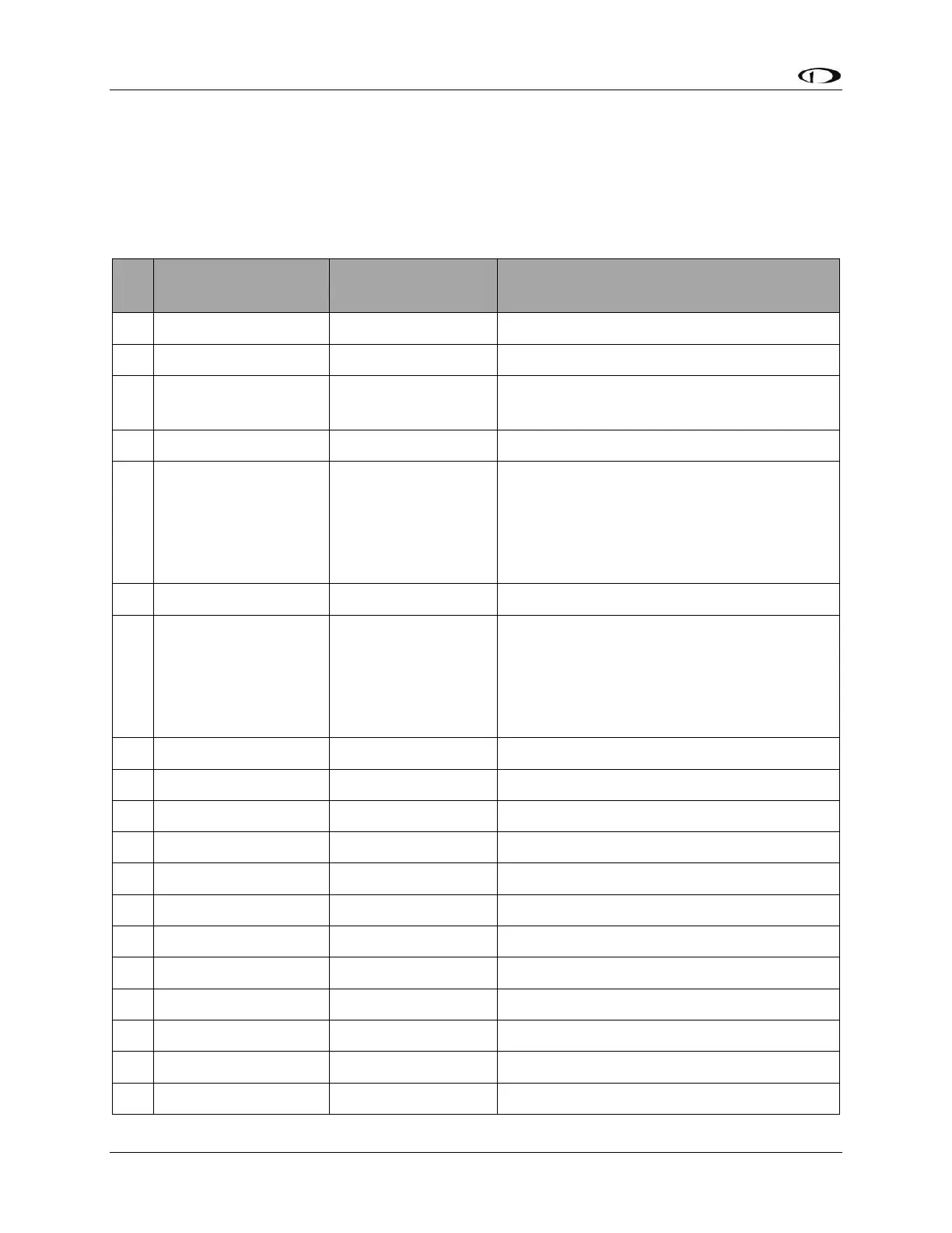
Certified GPS Only for ADS-B Out (see
explanation below)
SV-XPNDR-261/262
Serial RX
Data Input from SkyView Display(s):
Serial 1 – Pin 4 (Brown / Orange), or
Serial 2 – Pin 6 (Yellow / Orange), or
Serial 3 – Pin 8 (Green / Orange), or
Serial 4 – Pin 10 (Blue / Orange)
SV-XPNDR-261/262
Serial TX
Data Output to SkyView Display(s):
Serial 1 – Pin 3 (Brown / Violet), or
Serial 2 – Pin 5 (Yellow / Violet), or
Serial 3 – Pin 7 (Green / Violet), or
Serial 4 – Pin 9 (Blue / Violet)
Connect to Aircraft Ground
Connect to Aircraft Power
Optional: Not Commonly Connected
Optional: Not Commonly Connected
Optional: Not Commonly Connected