SV-XPNDR-261/262 Installation and Configuration
SkyView System Installation Guide - Revision AA 11-9
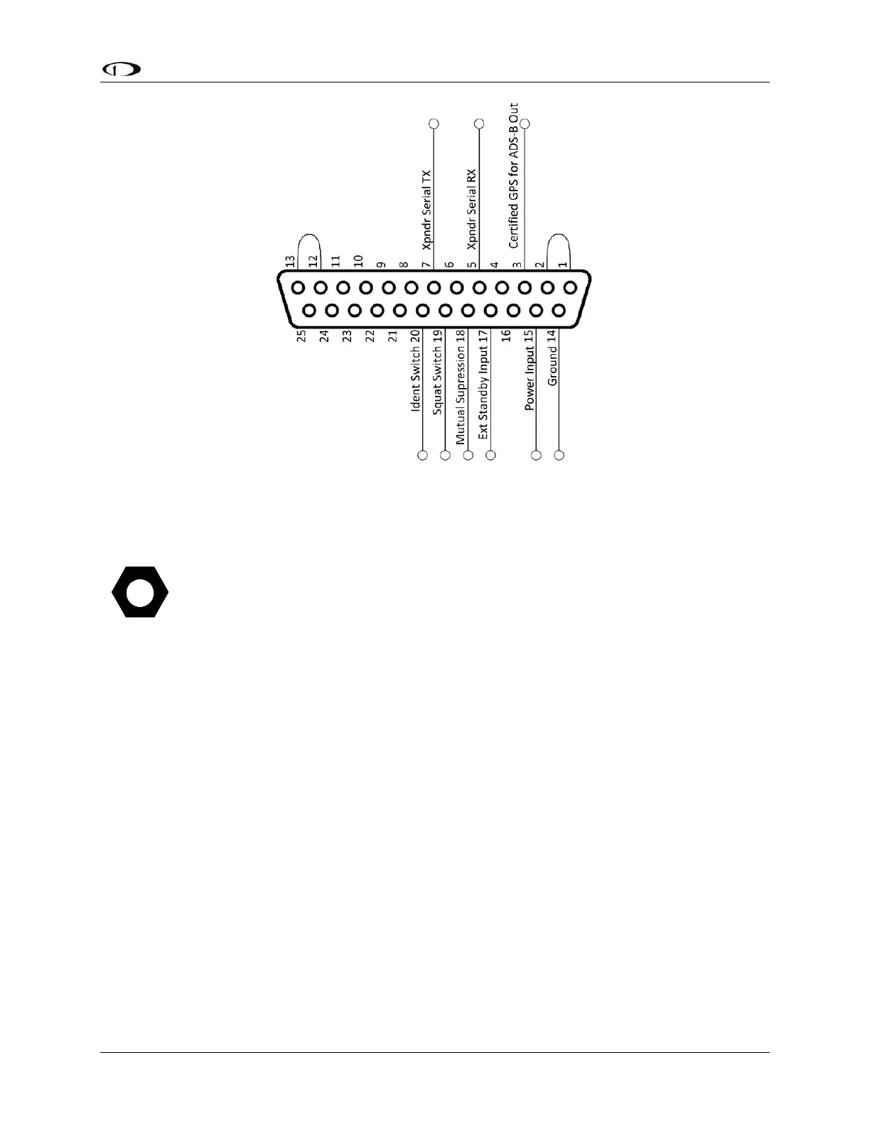
Figure 133 – All Possible SV-XPNDR-261/262 Connections (Rear Pin Insertion View)
Power / Ground Input
The power supply can be 11-33 Volts DC; no voltage adjustment is required. 20 AWG wire is
sufficient for wire runs up to 50’ for this application. Note that the SV-XPNDR-261/262 must be
connected to aircraft power – none of SkyView’s voltage outputs can provide a sufficient
amount of power to power the SV-XPNDR-261/262.
It is always good practice to use more than one ground path in an installation. With only one
wire there may be only a single grounding path for the SV-XPNDR-261/262, controller and
antenna. This can allow static electricity to build up and damage your SkyView display(s).
Ensuring that the mounting tray is grounded provides an adequate alternative ground path to
protect against such events. This is particularly important when the SV-XPNDR-261/262 is
mounted on a non-conducting surface, such as a composite structure, where the mounting tray
is often not grounded. Therefore, make sure that the mounting tray is grounded in addition to
having the ground wire connected as depicted above.
Note that Pin 1 and Pin 2 must be connected to each other as depicted above as
part of the wiring harness (they are not connected together inside the SV-XPNDR-
261/262).
Note that Pin 12 and Pin 13 must be connected to each other as depicted above as
part of the wiring harness (they are not connected together inside the SV-XPNDR-
261/262).