EasyManua.ls Logo

Dynon Avionics SkyView Classic - Page 389

Default Icon
573 pages
Print Icon
To Next Page IconTo Next Page
To Previous Page IconTo Previous Page
Loading...
SV-COM-C25 Installation and Configuration
SkyView System Installation Guide - Revision AA 16-7
Additional harness construction and wiring information can be found in Appendix C: Wiring and
Electrical Connections.
The SV-COM-PANEL has two (electrically identical) D9M connectors for connection to SkyView
Network and one D15M connector for connection with the SV-COM-425 and an optional
Frequency Flip/Flop pushbutton input.
The SV-COM-425 has one D15M connector for connection to the SV-COM-PANEL, power, audio,
and Push to Talk (PTT). A single BNC Female connector attaches to the antenna.
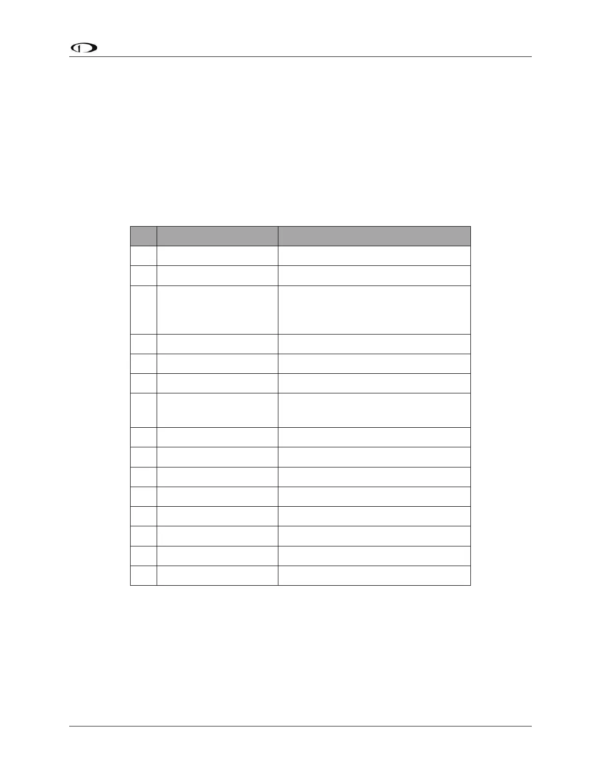
SV-COM-PANEL D15M Pinout
Pin
Function
Notes
1
Power In
From SV-COM-425 Pin 7
2
Ground In
From SV-COM-425 Pin 13
3
Ground Out
Optional - For Grounding Pin 7
(Flip/Flop Switch). Switch may also be
grounded locally.
4
Panel RX / 425 TX
From SV-COM-425 Pin 6
5
Panel TX / 425 RX
From SV-COM-425 Pin 14
6
Enable
From SV-COM-425 Pin 3
7
External Flip/Flop
(optional)
Push Button Normally Open to
Ground (Pin 3 or local ground)
8
No Connection
(Pin not used)
9
No Connection
(Pin not used)
10
No Connection
(Pin not used)
11
No Connection
(Pin not used)
12
No Connection
(Pin not used)
13
No Connection
(Pin not used)
14
No Connection
(Pin not used)
15
No Connection
(Pin not used)
Table 89 SV-COM-PANEL D15M Pinout

Table of Contents

Related product manuals